If you’re looking to add a little more sci-fi authenticity to your gaming setup, you could do much worse than this functional control lever replica that [ZapWizard] has entered into the Hackaday.io Sci-Fi Contest.
Taking inspiration from Disney’s The Mandalorian, this functional prop is almost identical to the throttle seen on the bridge of the Razor Crest gunship, piloted by the television show’s eponymous bounty hunter. The electronic heart of this build is relatively straightforward – a Trinket M0 measures the resistance of an ultra-thin potentiometer, and masquerades as a typical one-axis USB throttle.
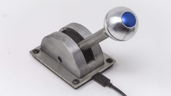
The mechanical components and aesthetically pleasing housing is where this project really shines. Helical 3D printed gears smooth out the movement of the solid aluminum throttle shaft, and a simple detent mechanism ‘catches’ the throttle at the middle point. The ballast and baseplate are cut from stainless steel, giving the throttle considerable heft, aiding in its stability on a tabletop (it’s also possible to secure it down using screws or powerful magnets). The throttle case is 3D printed and covered in aluminum foil tape, which is then chemically blackened and aged for that well-loved appearance.
Of course, the most iconic part of this build is the spherical knob, which screws onto the aluminum shaft for Grogu’s convenience. [ZapWizard] put in an order for one over at Custom 3D Stuff, and it absolutely ties the entire build together.
Interested in prop builds from the world of science-fiction, functional or otherwise? Then take a look through the entries in our Sci-Fi Contest. Or better yet, start building your own entry — there’s still about a month to go before the deadline.
Continue reading “Razor Crest Control Lever For The Grogu In Your Life”