With hackers and makers building custom computing devices that don’t necessarily follow conventional design paradigms, there’s been a growing demand for smaller and smaller keyboards. Many of the cyberdecks we’ve seen over the last couple of years have used so-called 60% or even 40% keyboards, and there’s been a trend towards repurposing BlackBerry keyboards for wearables and other pocket-sized gadgets. But what if you need something even smaller?
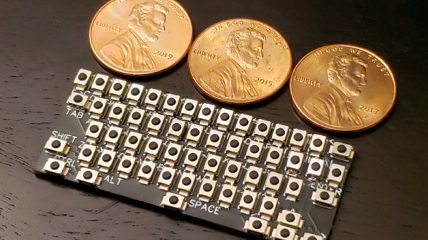
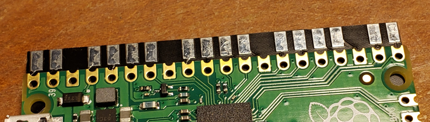
Enter this incredibly diminutive keyboard created by [TEC.IST]. With 59 keys crammed into an area scarcely larger than three US pennies, it may well be the smallest keyboard ever made. The PCB has been designed to mount directly onto the back of a Raspberry Pi Pico, which is running some CircuitPython code to read the switch matrix and act as a standard USB Human Interface Device. The board design files as well as the source code for the Pico have been released on the project’s Hackaday.io page, giving you everything you need to spin up your own teeny tiny input device.
Of course, you probably won’t be breaking any speed records when banging out text on this thing. We know from past Hackaday badges that an array of microswitches make for a functional, if somewhat unpleasant, method of text entry.
Continue reading “Raspberry Pi Pico Gets A Tiny Keyboard On Its Back”
 [Harry Gill] has you covered with