When catching public transport, it’s very helpful if the bus or train in question has a large display indicating the route or destination. While many transit lines now rely on flipdot or LED displays, the classic rollsign still gets the job done. [diorama111] wanted to emulate this on a model railroad, and set about building a simulacrum at tiny scale.
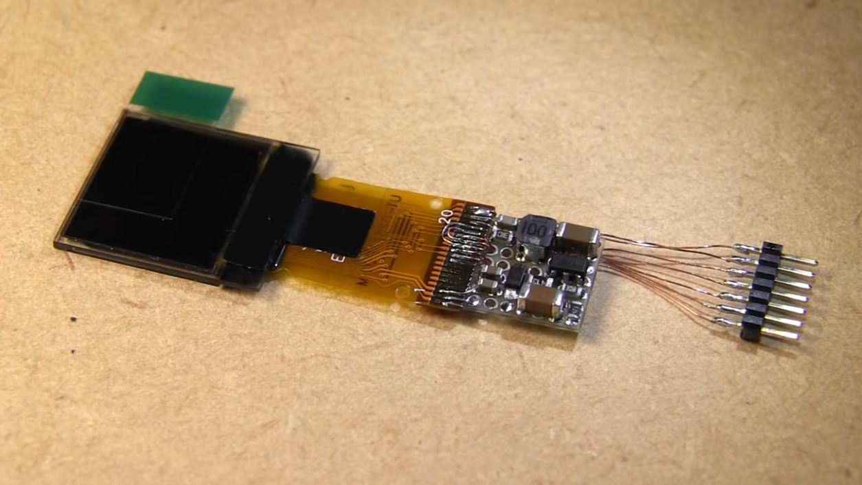
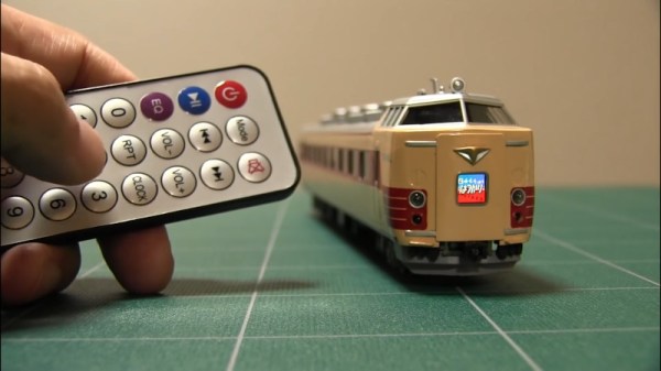
Intended to suit an HO-scale model train, the build makes use of a tiny 0.6 inch NHD-0.6-6464G OLED display. It’s wired up with a boost converter for power and hooked up to a tiny circuit consisting of an ATMEGA328p and an infrared receiver. The microcontroller is responsible for receiving commands from the remote control, and displaying the appropriate image on the screen. The hidden beauty of this one is well shown in the video below as [diorama111] cleanly and meticulously assembles the circuit on protoboard with just an iron and tweezers.
What makes this project great is how neatly it’s integrated into the body of the train. Nestled inside the locomotive, it almost looks like a stock part of the model. While the nature of the OLED display does come across a touch anachronistic, implementing the vertical scroll really does add a lot to the final effect.
We love to see creative scale modelling projects, and we’ve seen some great work from [diorama111] in the past, too. Video after the break.