Polyphonic Arduino Sketches

MIDUINO

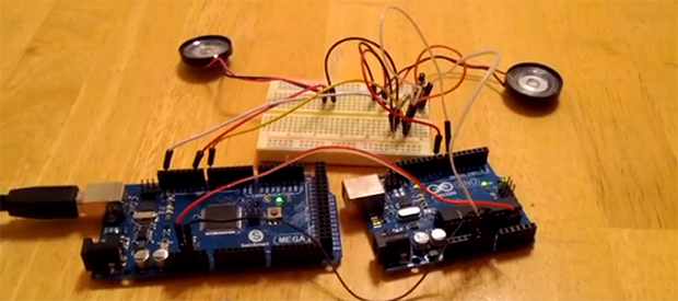
Creating music for the Arduino is simple – just use the tone() library – but it truthfully doesn’t sound that great. That’s because this library is monophonic, making chords difficult or at the very least sound a little weird. [Connor]’s miduino aims to change that, turning raw MIDI files into polyphonic Arduino sketches.

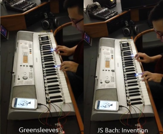
To convert MIDI files into Arduino sketches, [Connor] whipped up a Python script based on midiCSV that reads the notes and channels of a MIDI file and converts it into the language of the Arduino. Unlike the built-in tone() library, miduino is polyphonic making the music produced from any Arduino sound great. It’s basically the difference between writing music for a PC speaker and a true keyboard; sure, you’re only getting square waves, but it sounds much better.

Oddly, [Connor] hasn’t put up his Python script as far as we can tell. All the MIDI songs are being converted on [Connor]’s own Raspberry Pi. This is supposed to be cheaper than a VPS, and makes for a very cool project to boot.

Edit: Miduino isn’t polyphonic yet, but [Connor] says he should have that wrapped up in a week or two.

FlightDeck: A “Touchless” MIDI Controller

flightdeckmidi

[Edward] wanted a different way to modulate notes on his MIDI controller, so he decided to go touchless. Inspired by the pressure-sensing modulation on his Edirol keyboard, [Edward] aligned eight sensors into a row of playable notes and used infrared to sense the distance of a player’s hand from the keys. He also included some function buttons to cycle through 10 octaves and RGB LEDs beneath the table that perform alongside the music.

He chose SHARP GP2D120 sensors (direct link to datasheet) for their low threshold, which allowed the board to detect distance close to the sensor. Each is mounted onto a sheet of frosted acrylic along with its own “hold note” button and an LED to indicate the key is playing. The lower panel houses an Arduino Mega that drives the system along with an RGB LED strip and its driver board. [Edward] used Maxuino and OSC-Route to interface the Mega to a Max/MSP patch which runs the show.

Learn more about the FlightDeck’s features in a video demonstration of the controller and the software after the break, then check out some other MIDI hacks like this organ pedal or the Arduino-driven MIDI sequencer.

Continue reading “FlightDeck: A “Touchless” MIDI Controller”

Keyboard Spoofs 4 NES Controllers For Chiptune Goodness

NES-keyboard

This toy keyboard is being used to play music on an NES. As you probably already know, the hardware inside those original controllers was dead simple. They’re just a parallel to serial shift register that reads from all of the keys. To get this keyboard up and running [heavyw8bit] simply mounted eight chips inside the gutted toy, connecting two of them to the keyboard keys, and the rest to the array of push buttons he added to the right.

So what’s the point of using this as a quadruple game controller? Are you expecting to see what a full speed-run of Contra looks like using this as the controls? That’s not the point at all. This becomes a musician-friendly frontend for the NES synthesizer ROM called NESK-1. [heavyw8bit] wrote the game/program in order to allow you to use the original console hardware to play all of the sounds you know and love. Our favorite is the arpeggio example heard at about 2:35 into the clip after the break.

Continue reading “Keyboard Spoofs 4 NES Controllers For Chiptune Goodness”

Build A DIY Plate Reverb

PlateReverb

[Telegraphy] needed a reverb for his recording studio. There are hundreds of computer-based and standalone digital reverb systems out there, but he decided to build his own plate reverb. Reverb is an effect used in many professional audio and music recordings. Reverb adds thousands of echos to an audio signal. These echos decrease in amplitude over time. When used correctly, the effect is generally very pleasing to the ear.

A plate reverb uses a plate of sheet metal to generate the reverb. An audio driver is placed in contact with the metal plate. Audio is fed into the driver, which vibrates the plate. The vibrations travel along the surface of the plate, bouncing off the edges and reflecting back. These reflections are captured by a pickup, which then converts them to a voltage signal. The final reverb effect is actually created in the sound engineer’s mixing board when the “dry” source signal is mixed with the signal returned by the plate.

[Telegraphy’s] plate reverb was built almost entirely from found, Radio Shack, and hardware store parts. The plate and frame are from Lowes. The audio driver is a cut up speaker from an old car stereo. The pickup is a modified piezo transducer from Radio Shack. As [Telegraphy] states several times, there are a lot of differing opinions on exactly how and where to mount the various parts of the reverb. Any placement will generate some reverb. The question is where and how to mount things for the best effect. Much like beauty and the eye of the beholder, the answer to that question is in the ear of the listener.

Jump past the break for a tour of a slightly more involved plate reverb at Gallery Acoustics Studio.

Continue reading “Build A DIY Plate Reverb”

Circuit Bent Toy Keyboard Is MIDI Controlled

tymkrsKeyboard
The [Tymkrs] crew has come up with a pretty neat circuit bent toy keyboard hack. It’s been a while since we’ve seen a good circuit bending hack. This project started as a way to demo the [Tymkrs] “MIDI In Me” kit. A cheap toy keyboard was sacrificed for its sound generator board. Like many cheap mass-produced toys, this board is based upon a COB (chip on board) package. The silicon die of the main ASIC is placed directly on the PCB and bonded out to pads. A round epoxy blob keeps everything protected.

The [Tymkrs] found a number of the chip’s pads were unused in their keyboard. The inputs appeared to trigger drums, possibly for use in a different toy. These inputs, coupled with the ‘demo song’ buttons turned out to be the basis of this hack. MIDI input is sent to a Parallax Propeller. The prop runs a program that will set its I/O pins based upon MIDI Note On/Off commands. The I/O pins then drive transistors which inject signals into the button inputs of the keyboard.

The [Tymkrs] even went so far as to use a voltage divider on the main clock circuit of the keyboard. Changing the main clock causes a sort of pitch bend effect often heard with circuit bent toys. As with the buttons, a MIDI signal commands the prop to enable or disable oscillator signal injection. A potentiometer is used to tweak the oscillator frequency.

Continue reading “Circuit Bent Toy Keyboard Is MIDI Controlled”

LED-Guided Piano Instruction

LEDpianoGuide

[Kay Choe] can’t play the piano. Rather, he couldn’t, until he converted his keyboard to include LED-guided instruction. [Kay] is a microbial engineering graduate student, and the last thing a grad student can afford is private music lessons. With $70 in components and a cell phone, however, he may have found a temporary alternative.

The build works like a slimmed-down, real-world Guitar Hero, lighting up each note in turn. We’ve seen a project like this before, with the LEDs mounted above the keys. [Kay]’s design, however, is much easier to interpret. He embedded the LEDs directly into the keys, including ones above each black key to indicate the sharps/flats. An Android app takes a MIDI file of your choice and parses the data, sending the resulting bits into an IOIO board via USB OTG. A collection of shift registers then drives the LEDs.

For a complete novice, [Kay] seems to benefit from these lights. We are unsure whether the LEDs give any indication of which note to anticipate, however, as it seems he is pressing the keys after each one lights up. Take a look at his video demonstration below and help us speculate as to what the red lights signify. If you’re an electronics savant who wants to make music without practicing a day in your life, we recommend that you check out [Vladimir’s] Robot Guitar.

Continue reading “LED-Guided Piano Instruction”

Time-lapse Synthesizer Build Will Blow Your Mind

[themonkeybars] recently uploaded a time-lapse video of his DIY synthesizer build. First off the video itself is a pretty neat hack. An iPhone time-lapse app was used to capture one frame every 5 seconds. By the time the build was complete, approximately 46,000 frames had been snapped. This boiled down to over 43 minutes of youtube footage. [themonkeybars] didn’t work full time on the project, so the video covers about a year’s worth of work which we think makes it even cooler. The synth is also featured in much of the video’s soundtrack.

The synthesizer itself would be classified as an analog modular synth, a type we’ve seen before. Modular synthesizers are one of the earlier forms of electronic music. The synthesizer is composed of discrete modules such as oscillators, modulators, and filters. The modules may be housed in the same box, but they are not internally connected. All connections are made via front panel patch cables. This is where the term “Patch” came from. Continue reading “Time-lapse Synthesizer Build Will Blow Your Mind”