New Part Day: The RISC-V Lichee-RV Module And Dock

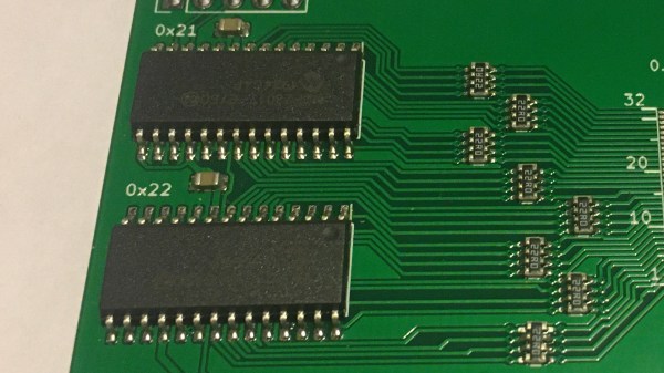
Sipeed have been busy leveraging developments in the RISC-V arena, with an interesting, low-cost module they call the Lichee RV. It is based around the Aliwinner D1 SoC (which contains a Pingtou Xuantie C906 for those following Chinese RISC-V processor development) with support for an optional NAND filesystem. This little board uses a pair of edge connectors, similar to the Raspberry Pi CM3 form factor, except it’s based around a pair M.2 connectors instead. The module has USB-C, an SPI LCD interface, as well as a TF card socket on-board, with the remaining interfaces provided on the big edge connector.

The minimalist Allwinner D1-based Lichee RV

So that brings us onto the next Sipeed board, the Lichee RV Dock which is a tiny development board for the module. This breaks out the HDMI, adds USB, a WiFi/Bluetooth module, audio driver, microphone array interface and even a 40-way GPIO connector. Everything you need to build your own embedded cloud-connected device.

Early adopters beware, though, Linux support is still in the early stages of development, apparently with Debian currently the most usable. We’ve not tested one ourselves yet, but it does look like quite useful for those projects with a small budget and not requiring the power-hungry multi-core performance of a Raspberry Pi or equivalents.

We’ve seen the Sipeed MAix M1 AI Module hosted on a Pi Hat a couple of years ago, as well as a NES emulator running on the Sipeed K210. The future for RISC-V is looking pretty good if you ask us!

Thanks [Maarten] for the tip!

Planning Custom Aluminum Enclosures With OpenSCAD

We’ve seen a number of projects over the years that let you create custom enclosures using OpenSCAD, and for good reason. The parametric CAD tool is ideal for generating 3D models based on user-adjustable variables, and if you leverage its integrated Customizer, producing a bespoke box is as easy as moving some sliders around. The resulting files get sent off to the 3D printer, and you’re set. But what if you’re looking for a custom enclosure that’s not so…plastic?

In that case, AlClosure by [0xPIT] might be the answer. Rather than generating STL files intended for your 3D printer, the code is written to help you design an enclosure made from aluminum sheets. The top and bottom panels are intended to be cut from 1.5 mm – 2.5 mm sheets, while the sides are made from thicker 5 mm – 8 mm stock to accept a machined pocket that holds the front and rear inserts.

Since it’s OpenSCAD, much of the design is governed by variables which you can tweak. Obviously the outside dimensions of the enclosure can be changed in a flash, but it’s just as easy to modify the thickness of the aluminum sheet being used, or the size of the screw holes. [0xPIT] has also done a great job of documenting the code itself, so you’ll know exactly what you’re modifying.

Obviously, you’ll need the ability to cut and machine aluminum to actually utilize this project. The code itself is really just a way to conceptualize the design and get your dimensions figured out ahead of time. But as we were recently reminded by the keynote presentation [Jeremy Fielding] gave at the 2021 Remoticon, this sort of early prototyping can often save you a lot of headaches down the line.

All Hail Your New Giant 555 Timer Overlord

You asked for it, and now you’ve got it. It’s taken more than a decade of accumulated complaining, but this gigantic 555 timer IC has finally gathered enough psychokinetic energy to take corporeal form and demand fealty from the readers of Hackaday.

Or not. The less exciting explanation is that creator [Rudraksha Vegad] was looking for a way to combine his interests in discrete electronic components and woodworking. The result is an incredible build that’s more than just a conversation starter; this desktop-sized version of the iconic integrated timer circuit is fully functional. You can even hook it up to a breadboard, assuming you’ve got some alligator clips handy.

Lifting the lid on this wooden “chip” uncovers an intricate hand-wired array of discrete components that stand in for the microscopic goings on inside the real thing. He’s even gone through the trouble of recreating the symbols for the comparators and flip-flops that you’d see in a diagram of a 555 using wooden shapes to elevate their respective components. It might not fit the classical definition, but surely this must count as some form of circuit sculpture.

[Rudraksha] credits several other projects for not just inspiring him to create his own mega 555, but for helping him wrap his head around the internal workings of everyone’s favorite IC. Using components he salvaged from old hardware, he says the project ended up being very educational for him. These days, when most makers are more likely to reach for a microcontroller than a logic chip, spending some quality time with transistors and passives can be quite illuminating.

Continue reading “All Hail Your New Giant 555 Timer Overlord”

A Particularly Festive Chip Decapping

As we approach the moment in the year at which websites enter a festive silly season of scrambling to find any story with a festive angle, we’re pleased to see the ever-reliable [Ken Shirriff] has brought his own take on Christmas tech to the table with a decapping of the UM66T melody chip that has graced so many musical greeting cards.

The surprise in this age of ubiquitous microcontrollers is that this is not a smart device; instead it’s a single-purpose logic chip whose purpose is to step through a small ROM containing note values and durations, driving a frequency generator to produce the notes themselves. The frequency generator isn’t the divider chain from the RC oscillator that we might expect, instead it’s a shift register arrangement which saves on the transistor count.

Although the UM66 is a three-pin device, there are a few other pins on the die. These are likely to be for testing. As a 30+ year old product its design may be outdated in 2021, but it’s one of those chips that has survived without being superseded because it does its task without the need for improvement. So when you open a card and hear the tinny tones of a piezo speaker this holiday season, spare a thought for the ingenuity of the design behind the chip that makes it all possible.

3D Printed Parts Hold Up To Steam Heat

Steam turbines are at the heart of all manner of industrial machinery, particularly that used for power generation. [Integza] decided he needed to better understand this technology, and decided to build one himself – using 3D printing, at that. 

First, a steam source was needed, with a pressure cooker on an electric stove pressed into service. The steam was passed out via a nozzle printed in resin, which better resists heat than most FDM-printed parts. Similarly, a turbine wheel was printed in resin as well, with the steam outlet pointed directly at its vanes.

To really stress test the parts, more steam was required.  To achieve this, hydrogen peroxide was pumped through a manganese dioxide catalyst impregnated into steel wool to create steam. This made an absolute mess, but the printed parts nevertheless survived.

The steam turbine didn’t do any useful work, but was able to survive the high temperatures at play. We’d love to see such a device actually used to bear some load, perhaps in some sort of 3D printed power generating turbine design.

Alternatively, if you prefer your steam turbines more classically driven, consider this build. Video after the break.

Continue reading “3D Printed Parts Hold Up To Steam Heat”

Nixie clock from a frequency counter

A Nixie Clock, The Hard Way

Notice: no vintage Hewlett Packard test equipment was harmed in the making of this overly complicated Nixie clock. In fact, if anything, the HP 5245L electronic counter came out better off than it went into the project.

HP 5245 hand-wired backplane
Beautiful hand-wired backplane in the HP 5245 counter.

We mention the fate of this instrument mainly because we’ve seen our fair share of cool-looking-old-thing-gutted-and-filled-with-Arduinos projects before, and while they can be interesting, there’s something deeply disturbing about losing another bit of our shared electronic heritage. To gut this device, which hails from the early 1960s and features some of the most beautiful point-to-point backplane wiring we’ve ever seen, would have been a tragedy, one that [Shahriar] wisely avoided.

After a bit of recapping and some power supply troubleshooting, the video below treats us to a tour of the Nixie-based beauty. It’s a wonderful piece, and still quite accurate after all these decades, although it did need a bit of calibration. Turning it into a clock non-destructively required adding a little bit of gear, though. Internally, [Shahriar] added a divide-by-ten card to allow the counter to use an external 10-MHz reference. Externally, an ERASynth++ programmable signal generator was used to send a signal to the counter from 0 Hz to 23,595.9 kHz, ramping up by 100 Hz every second.

The end result is the world’s most complicated 24-hour clock, which honestly wasn’t even the point of the build at all. It was to show off the glorious insides of the counter, introduce us to some cool new RF tools, and as always with [Shahriar]’s videos, to educate and inform. We’ve always enjoyed his wizardry, from his look into automotive radars to a million-dollar scope teardown, and this was another great project.

Continue reading “A Nixie Clock, The Hard Way”

A Slim 7400 Logic VGA Board For All Your Retro Needs

Over the years we’ve seen a number of hackers generate VGA with 74xx logic chips, but they’ve generally not been the most practical of builds. Often put together as part of a competition or purely for the challenge, these circuits are usually implemented in a mass of jumper wires and often take up multiple breadboards. Not exactly something you can toss in a drawer when you’re done with it.

But the Vectron VGA Plus, created by prolific hacker [Nick Bild], manages to improve on things considerably. Designed specifically to be smaller and simpler than its predecessors, the custom PCB contains far fewer chips than we’re used to seeing for this kind of thing. At the same time it provides a handy header row along the bottom that allows the user to connect whatever they’re working on, from microcontrollers to retro computers.

When your breadboard looks like this, it’s time for a PCB.

It looks like the PCB could still be shrunk down considerably if you’re really looking to maximize desk space, but we imagine for his purposes, [Nick] felt this was more than compact enough. Especially when you look at what the same circuit looked like during the breadboard phase. Yikes.

So, what did it take to simplify this 640 x 480 VGA interface? The short answer is adding more RAM. Wherever possible, dedicated hardware was replaced with software operations that could be performed by the externally connected device. [Nick] has provided some sample code for the Arduino that lets the microcontroller push data into the board’s memory and take control.

We can trace the origins of this project back a few years, to when [Nick] was working on adding an LCD to his homebrew 6502 computer. A few months later he put together the earlier version of this board, the Vectron VGA, before switching gears and handing VGA generation duty over to a FPGA. We’re excited to see the next evolution of this project, and given the track record of this particular hacker, we shouldn’t have to wait long before it hits our inbox.