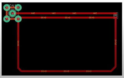
A graphic showing the suggested footprint dimensions for 0402 parts

Want Better 0402 Reflow? Consider These Footprints!

Assembling with a stencil is just that much more convenient – it’s a huge timesaver, and your components no longer need to be individually touched with a soldering iron for as many times as they have pads. Plus, it usually goes silky smooth, the process is a joy to witness, and the PCB looks fantastic afterwards! However, sometimes components won’t magically snap into place, and each mis-aligned resistor on a freshly assembled board means extra time spent reflowing the component manually, as well as potential for silent failures later on. In an effort to get the overall failure rate down, you will find yourself tweaking seemingly insignificant parameters, and [Worthington Assembly] proposes that you reconsider your 0402 and 0201 footprints.

Over the years, they noticed a difference in failure rates between resistor&capacitor footprints on various boards coming in for assembly – the size and positioning of the footprint pads turned out to be quite significant in reducing failure rate, even on a tenth of millimeter scale. Eagle CAD default footprints in particular were a problem, while a particular kind of footprint never gave them grief – and that’s the one they recommend we use. Seeing the blog post become popular, they decided to share their observations on 0201 as well, and a footprint recommendation too. Are your 0402 resistors giving you grief? Perhaps, checking the footprints you’re using is a good first step.

The 0402 and 0201 components are in a weird spot, where soldering iron assembly is no longer really viable, but the stencil+reflow approach might not be unilaterally successful when you start off – fortunately, that’s where writeups like these come in. Interested in learning stenciling? Get some solder paste, and read up on all the different ways you can put it onto your boards.

Showing KiCanvas board viewer component inside a browser window, with a board being displayed and toggleable layers

KiCanvas Helps Teach And Share KiCad Projects In Browsers

KiCad is undeniably the hacker favourite when it comes to PCB design, and we’ve built a large amount of infrastructure around it – plugins, integrations, exporters, viewers, and much more. Now, [Stargirl Flowers] is working on what we could call a web viewer for KiCad files – though calling the KiCanvas project a “KiCad viewer” would be an understatement, given everything it aims to let you do. It will help you do exciting things like copy-pasting circuits between KiCad and browser windows, embed circuits into your blog and show component properties/part numbers interactively, and of course, it will work as a standalone online viewer for KiCad files!

Continue reading “KiCanvas Helps Teach And Share KiCad Projects In Browsers”

ESP8266 Coaster Keeps Your Drink Warm

Looking for the perfect winter desk accessory? [Wq] has created a beautiful coaster made out of PCBs  that can keep your drink warm with an internal heater. (Chinese).

An ESP8266 sits as the main controller, with an additional MQTT control option, where the whole unit is powered over a USB-C connection. On board PCB traces, in the shape of a Hilbert curve, create the heating element used to heat beverages placed on the coaster, where [Wq] reports a measured resistance of the PCB trace network at 1.2 ohms. [Wq] writes that an AON6324 MOSFET replaces the D4184 that was previously being used, but might need some testing to get working properly. There are two capacitive touch sensors which has a TTP223E capacitive touch controller attached to detect input, with a multi-colored FM-3528 RGB LED for user feedback.

We love the artistry that went into building the coaster. For adventurous hackers wanting to build their own, the bill of materials (BOM), source code and board files are all available. We’ve seen everything from coasters and to PCB reflow boards, so it’s nice to see experimentation with a combination of these ideas.

PCB Pen Holder Is Over The Top

Like most of us, [Arnov] used a spare coffee mug to hold pens on his desk. But there has to be a better way, right? Surely if you build a better mouse trap… or, in this case, a pen holder. He’d be the first to admit that he might have gotten a little carried away, but the result is an attractive pen holder made from PCB material, one of which is actually an active circuit board.

The pen holder has some power management, as there’s a rechargeable battery that allows it to charge devices such as a smartphone or an embedded board. The power is also available for LEDs in the pen holder. The PCBs are bound together with 3D printed brackets.

The non-functioning PCBs still have patterns etched to make them more interesting looking. This is one of those things that isn’t technically a big deal, but we really liked the look of it, which was quite professional. We’ve seen PCBs used as enclosures before, but making the pattern and improving light transmission by removing the solder mask were nice touches.

If you don’t like the idea of making enclosures from PCB material, don’t forget they can form other components, as well. Clever arrangements can build resistors, capacitors, and inductors not to mention exotic transmission line elements.

Continue reading “PCB Pen Holder Is Over The Top”