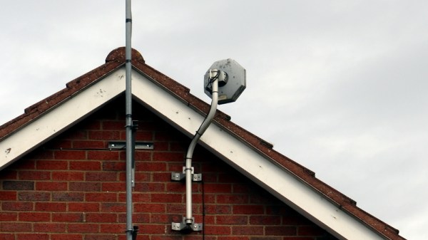
The Simplest Microwave Receiver

We are used to microwave receivers requiring complex chipsets and exacting PCB layouts, but as [CHZ-soft] has shown, it does not always have to be that way. With nothing more complex than a germanium point-contact diode and an oscilloscope, you can quickly, easily, and cheaply resolve microwave signals, as we are shown with a 2.4GHz wireless mouse.

Of course, there’s nothing new here, what we’re being shown is the very simplest incarnation of a crystal set. It’s a wideband device, with only the length of the wires providing any sort of resonance, but surprisingly with the addition of a very selective cavity resonator it can be turned into a useful receiver. Perhaps the most interesting take-away is that the germanium point-contact diode — once a ubiquitous component — has almost entirely disappeared. In most applications it has been supplanted by the Schottky diode, but even those usually don’t quite possess the speed in the point contact’s home ground of radio detection. This is a shame, because there are still some bench-level projects for which they are rather useful.

So if you have a point contact diode and AM radio doesn’t attract, give it a go as a microwave detector. And if the point contact diode has attracted your interest then you may want to read our piece on Rufus Turner, who brought us its archetype, the 1N34A.

Via Hacker News.

Credit Card Chip Used To Make Crystal Radio

Perhaps the simplest radio one can build is the crystal radio. Using a diode as a detector, the design generally uses less than 10 components and no battery, getting its power to run from the radio signal itself. [Billy Cheung] decided to build a crystal radio using a rather unconventional detector – the smart chip in a common credit card.

This is possible because the smart chip on many credit cards contains a diode. It’s then a simple matter of hooking up the right pads on the credit card to the rest of a crystal radio circuit, and you’re all set. Of course, [Billy] goes the whole hog, building the entire radio on a single credit card. Other cards are cut up to create bobbins for winding coils to form a variable inductor, used to tune the radio. Doing this allows for a much cleaner, thinner design, rather than using a variable capacitor which is comparatively hard to find. Turning the dial allows stations to be tuned in, and with a high impedance earbud hooked up, you’re listening to AM radio. Oh, and don’t forget an antenna!

[Billy] breaks down the details for anyone wishing to replicate the feat, going so far as to wind the coils in real time in his Youtube video. Cutting templates and other details are available on Github. While it’s not going to be the most replicated hack, as it requires the destruction of a credit card to achieve, we love the ingenuity. And, if society does collapse, we’ll all have a great source of diodes when the ATMs have all become useless. Video after the break.

[Thanks to Zane Atkins for the tip!]

Continue reading “Credit Card Chip Used To Make Crystal Radio”

Receive Analog Video Radio Signals From Scratch

If you’ve been on the RTL-SDR forums lately you may have seen that a lot of work has been going into the DragonOS software. This is a software-defined radio group that has seen a lot of effort put into a purpose-built Debian-based Linux distribution that can do a lot of SDR out of the box. The latest and most exciting project coming from them involves a method for using the software to receive and demodulate analog video.

[Aaron]’s video (linked below) demonstrates using a particular piece of software called SigDigger to analyze an incoming analog video stream from a drone using a HackRF. (Of course any incoming analog signal could be used, it doesn’t need to be a drone.) The software shows the various active frequency ranges, allows a user to narrow in on one and then start demodulating it. While it has to be dialed in just right to get anything that doesn’t look like snow, [Aaron] is able to get recognizable results in just a few minutes.

Getting something like this to work completely in software is an impressive feat, especially considering that all of the software used here is free. Granted, this wouldn’t be as easy for a digital signal like most TV stations broadcast, but there’s still a lot of fun to be had. In case you missed the release of DragonOS, we covered it a few weeks ago and it’s only gotten better since then, with this project just as one example.

Continue reading “Receive Analog Video Radio Signals From Scratch”

WiFi Goes Open

For most people, adding WiFi to a project means grabbing something like an ESP8266 or an ESP32. But if you are developing your own design on an FPGA, that means adding another package. If you are targeting Linux, the OpenWifi project has a good start at providing WiFi in Verilog. There are examples for many development boards and advice for porting to your own target on GitHub. You can also see one of the developers, [Xianjun Jiao], demonstrate the whole thing in the video below.

The demo uses a Xilinx Zynq, so the Linux backend runs on the Arm processor that is on the same chip as the FPGA doing the software-defined radio. We’ll warn you that this project is not for the faint of heart. If you want to understand the code, you’ll have to dig into a lot of WiFi trivia.

Continue reading “WiFi Goes Open”

ATMega328 SSB SDR For Ham Radio

The humble ATmega328 microcontroller, usually packaged as an Arduino Uno, is the gateway drug for millions of people into the world of electronics and embedded programming. Some people just can’t pass up the challenge of seeing how far they can push the old workhorse, and it looks like [Guido PE1NNZ] is one of those. He has managed to implement a software-defined SSB ham radio transceiver for the HF bands on the ATMega328, and it looks like the project is going places.

The radio started life as a QRP Labs QCX, a $49 single-band CW (morse code) HF transceiver kit that is already one of the cheapest ways to get on the HF bands. [Guido] reduced the part count of the radio by about 50%, implementing much of the signal processing digitally on the ATmega328. On the transmitter side, the SSB signal is generated by making slight frequency changes to a Si5351 clock generator using 800kbit/s I2C, and controlling a very efficient class-E RF power amplifier with PWM for about 5W of output power. The increased efficiency means that there is no need for the bulky heat sink usually seen on SSB radios. The radio is continuously tunable from 80m to 10m (3.5 Mhz – 30 Mhz), but it does require plugging in a different low pass filters for each band. Continue reading “ATMega328 SSB SDR For Ham Radio”

This Frequency Generator Knows How To Get Down

What kind of clever things could you do with a signal that had a period of 2 hours? Or 20? Any ideas? No seriously, tell us. Because [Joseph Eoff] has come up with a way to produce incredibly low frequency signals that stretch out for hours, and we’d love to figure out what we can do with it.

To be fair, it’s not like [Joseph] has any ideas either. He thought it would be an interesting project, and figures now that he has the technology, maybe some application will come to him. They say that if you’ve got a hammer everything looks like a nail, so maybe the next project he sends our way will be a sinusoidal fish feeder.

[Joseph] says doing the software side of things with Pure Data wasn’t a problem, but getting it out of the computer proved to be tricky. It turns out that your average computer sound card isn’t equipped to handle frequencies down into the millihertz range (big surprise), so they need to be coaxed out with some extra hardware. Using a simple circuit not unlike an AM demodulator, he’s able to extract the low-frequency signal from a 16 kHz carrier.

So if you ever find yourself in need of a handful of hertz, now you’ve got the tool to generate them. At least it’s more practical than how they used to generate low frequency signals back in the 1900s.

An Arduino As A PLL

At the heart of many amateur radio and other projects lies the VFO, or Variable Frequency Oscillator. Decades ago this would have been a free-running LC tuned circuit, then as technology advanced it was replaced by a digital phase-locked-loop frequency synthesiser and most recently a DDS, or Direct Digital Synthesis chip in which the waveform is produced directly by a DAC. The phase-locked loop (PLL) remains a popular choice due to ICs such as the Si5351 but is rarely constructed from individual chips as it once might have been. [fvfilippetti] has revisited this classic circuit by replacing some of its complexity with an Arduino (Spanish language, Google Translate link).

The internals of a PLL frequency synthesiser
The internals of a PLL frequency synthesiser. Image by Chetvorno – CC0

A PLL is a simple circuit in which one oscillator is locked to another by controlling it with a voltage derived from comparing the phase of the two. Combining a PLL with a set of frequency dividers creates a frequency synthesiser, in which a variable frequency oscillator can be locked to a single frequency crystal with the output frequency set by the division ratios. The classic PLL chip is the CMOS 4046 which would have been combined with a pile of logic chips to make a frequency synthesiser. The Arduino version uses the Arduino’s internal peripherals to take the place of crystal oscillator, dividers, and phase comparator, resulting in an extremely simple physical circuit of little more than an Arduino and a VCO for the 40 metre amateur band. The code can be found on GitLab, should you wish to try for yourself.

It would be interesting to see how good this synthesiser is at maintaining both a steady frequency and minimal phase noise. It’s tempting to think of such things as frequency synthesisers as a done deal, so it’s always welcome to see somebody bringing something new to them. Meanwhile if PLLs are new to you, we have just the introduction for you.