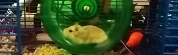
[Michelle Leonhart] has two Roborovski hamsters (which, despite the name, are organic animals and not mechanical). She discovered that they seem to run on the hamster wheel all the time. A little Wikipedia research turned up an interesting factoid: This particular breed of hamster is among the most active and runs the equivalent of four human marathons a night. Of course, we always believe everything we read on Wikipedia, but not [Michelle]. She set out to determine if this was an accurate statement.
She had already added a ball bearing to the critters’ wheel to silence it by cannibalizing an old VCR. What she needed was the equivalent of a hamster pedometer. A Raspberry Pi and a Hall effect sensor did the trick. At least for the raw measurement. But it still left the question: how much distance is a hamster marathon?
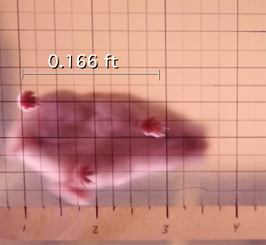
 [Michelle] went all scientific method on the question. She determined that an average human female’s stride is 2.2 feet which works out to 2400 strides per mile. A marathon is 26.2 miles (based on the distance Pheidippides supposedly ran to inform Athens of victory after the battle of Marathon). This still left the question of the length of a hamster’s stride. Surprisingly, there was no definitive answer, and [Michelle] proposed letting them run through ink and then tracking their footsteps. Luckily, [Zed Shaw] heard about her plan on Twitter and suggested pointing a webcam up through the plastic bottom of the cage along with a scale. That did the trick and [Michelle] measured her hamster’s stride at about 0.166 feet (see right).
Now it was a simple matter of math to determine that a hamster marathon is just under 10,500 steps. Logging the data to SQLite via ThingSpeak for a month led [Michelle] to the conclusion: her hamsters didn’t run 4 marathon’s worth of steps in a night. In fact, they never really got much over 2 marathons.
Does [Michelle] have lazy hamsters, or did she just add to our body of scientific knowledge about rodents? We don’t know. But we couldn’t help but admire her methods and her open source data logging code would probably be useful for some non-hamster activities.
If you are super competitive, you could use [Michelle’s] data to handicap yourself and challenge your pets to a race. But it would probably be cooler to build them their own Starship Trooper-style walkers. Either way, you can check out [Michelle’s] little marathon runners in the video below.
https://vine.co/v/enpFetTQD75