The various Raspberry Pi camera modules have become the default digital camera hacker’s tool, and have appeared in a huge number of designs over the past decade. They’re versatile and affordable, and while the software can sometimes be a little slow, they’re also of decent enough quality for the investment. Making a Pi camera can be annoying though, because different screens, lenses, and modules have their own mounting requirements. [Jacob David C Cunningham] has a solution here, with a modular Raspberry Pi camera, as an experimentation platform for different screens and lenses.
It takes the form of a central unit that holds the Pi and its support components, and front and rear modules for the screens or displays. Examples are given using the HQ and non-HQ modules, as well as with round or rectangular displays.
When designing a camera for 3D printing it’s a very difficult task, to replicate or exceed the industrial design of commercial cameras. Few succeed, and we’d include ourselves among that number. But this one comes close; it looks like a camera we’d like to use. We like it.
The Raspberry Pi has brought digital camera experimentation within the reach of everybody, with its combination of an accessible computing platform and some almost-decent camera sensors. If there’s a flaw in the Pi as a camera though, it lies in the software, which can be slow and frustrating to use. [Martijn Braam] is here with an interesting project that might yield some useful results in this direction, he’s making a Raspberry Pi studio camera.
His camera hardware is very straightforward, a Pi 5 and touchscreen with the HD camera module in a rough but serviceable wooden box. The interesting part comes in the software, in which he’s written a low-latency GUI over an HDMI output camera application. It’s designed to plug into video mixing hardware, and one of the HDMI outputs carries the GUI while the other carries the unadulterated video. We can see this used to great effect with for example OBS Studio. It’s for now a work in progress as you can see in the video below the break, but we expect that it can only get better.
The video below exposes the obvious flaw in many Pi camera setups, that the available lenses don’t match the quality of the sensor, in that good glass ain’t cheap. But we think it’s one to watch, and could provide competition for CinePi.
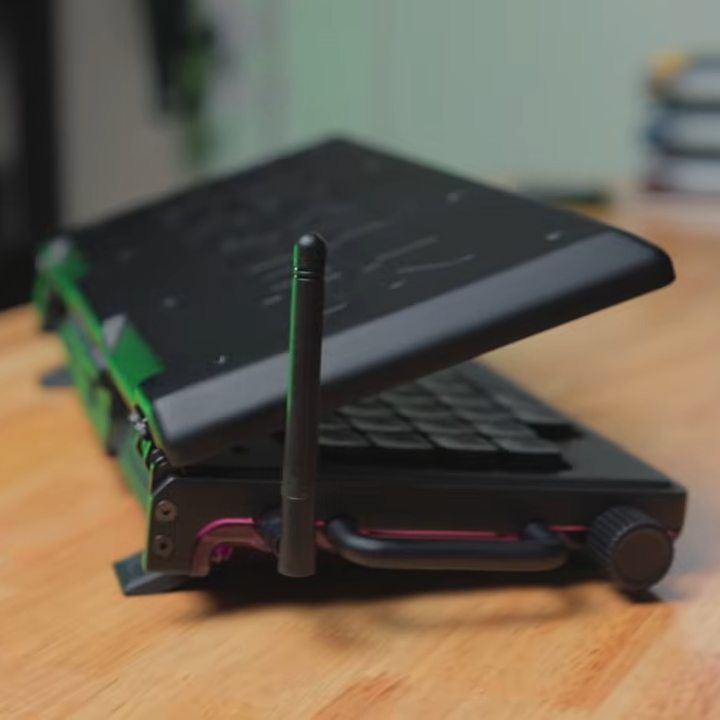
Cyberdecks are great projects, and [Salim Benbouziyane]’s scratch-built CM Deck is a fantastic specimen. It’s a clamshell-style cyberdeck with custom split keyboard, trackpad, optional external WiFi antenna, and some slick underlighting thanks to a translucent bottom shell. There’s even a hidden feature that seems super handy for a cyberdeck: a special USB-C port that, when plugged in to another host (like another computer), lets the cyberdeck act as an external keyboard and trackpad for that downstream machine.
The CM Deck is built around the Raspberry Pi Compute Module 5, which necessitates a custom PCB but offers more design freedom.
Notably, the CM Deck is custom-built around the Raspberry Pi Compute Model 5. When we first peeped the CM5 the small size was striking, but of course that comes at the cost of having no connectors, supporting hardware, or heat management. That’s something [Salim] embraced because it meant being able to put connectors exactly where he wanted them, and not have to work around existing hardware. A custom PCB let him to lay out his cyberdeck with greater freedom, less wasted space, and ultimately integrate a custom-built keyboard (with RP2040 and QMK firmware).
Even the final enclosure is custom-made, with 3D printing being used to validate the design and PCBway providing finished plastic shells in addition to manufacturing the PCBs. [Salim] admits that doing so was an indulgence, but his delight at the quality of the translucent purple undercarriage is palpable.
[Salim]’s video (embedded below) is a deep dive into the whole design and build process, and it’s a great watch for anyone interested in the kind of work and decisions that go into making something like this. Experienced folks can expect to nod in sympathy when [Salim] highlights gotchas like doing CAD work based on the screen’s drawings, only to discover later that the physical unit doesn’t quite match.
The GitHub repository contains the design files for everything, so give it a browse if you’re interested. [Salim] is no stranger to clean builds, so take a moment to admire his CRT-style Raspberry Pi terminal as well.
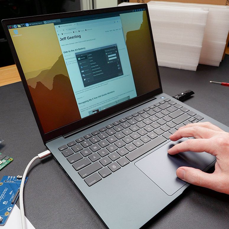
The Argon40 ONE UP unsurprisingly looks like a laptop. (Credit: Jeff Geerling)
The Raspberry Pi Compute Module form factor is a tantalizing core for a potential laptop, with a CM5 module containing a fairly beefy SoC and RAM, with depending on the exact module also eMMC storage and WiFi. To turn this into a laptop you need a PCB to put the CM5 module on and slide it into a laptop shell. This is in effect what [Argon40] did with their crowdfunded ONE UP laptop, which [Jeff Geerling] has been tinkering with for a few weeks now, with some thoughts on how practical the concept of a CM5-based laptop is.
Most practical is probably the DIY option that [Jeff] opted for with the ‘Shell’ version that he bought, as that meant that he could pop in one of the CM5s that he had lying around. The resulting device is totally functional as a laptop, with all the Raspberry Pi 5 levels of performance you’d expect and with the repair-friendliness of a Framework laptop.
If you’re buying the Core version with the 8 GB CM5 module and 256 GB NVMe SSD included, you’re looking at €475 before shipping or the equivalent in your local currency. This puts it unfortunately in the territory of budget x86 laptops and used Apple MacBooks, even before taking into account the current AI-induced RAMpocalypse that’d push [Jeff]’s configuration to $600 if purchased new, with prices likely to only go up.
Even if this price isn’t a concern, and you just want to have a CM5-based laptop, [Jeff]’s experience got soured on poor customer support from [Argon40] and above all the Raspberry Pi’s arch nemesis: the inability to do sleep mode. With the lid closed it runs at 3.3 W idle, but that’ll run down the battery from 100% to flat in about 17 hours. Perhaps if Raspberry Pi added sleep states to their systems would it make for a good laptop core, as well as for a smartphone.
When [101 Things] didn’t want to copy Morse code, he decided to build a Pi Pico system to read it for him. On the face of it, this doesn’t seem particularly hard, until you look at the practical considerations. With perfectly timed dots and dashes, it would be trivial. But in real life, you get an audio signal. It has been mangled and mixed with noise and interference as it travels through the air. Then there’s the human on the other end who will rarely send at a constant speed with no errors.
Once you consider that, this becomes quite the project, indeed. The decoder captures audio via the Pi’s analog-to-digital converter. Then it resamples the input, applies an FFT, and converts the output via a complex classification pipeline that includes, among other things, Bayesian decoding. Part of the pipeline makes simple typo corrections. You can see the device do its thing in the video below.
Hackers have been building their own basic oscilloscopes out of inexpensive MCUs and cheap LCD screens for some years now, but microcontrollers have recently become fast enough to actually make such ‘scopes useful. [NJJ], for example, used a pair of Raspberry Pi Picos to build Picotronix, an extensible combined oscilloscope and logic analyzer.
This isn’t an open-source project, but it is quite well-documented, and the general design logic and workings of the device are freely available. The main board holds two Picos, one for data sampling and one to handle control, display, and external communication. The control unit is made out of stacked PCBs surrounded by a 3D-printed housing; the pinout diagrams printed on the back panel are a helpful touch. One interesting technique was to use a trimmed length of clear 3D printer filament as a light pipe for an indicator LED.
Even the protocol used to communicate between the Picos is documented; the datagrams are rather reminiscent of Ethernet frames, and can originate either from one of the Picos or from a host computer. This lets the control board operate as an automatic testing station reporting data over a wireless or USB-connected network. The display module is therefore optional hardware, and a variety of other boards (called picoPods) can be connected to the Picotronix control board. These include a faster ADC, adapters for various analog input spans, a differential analog input probe, a 12-bit logic state analyzer, and a DAC for signal generation.
The Raspberry Pi has been a revolutionary computer in the maker space, providing a full Linux environment, GUI, and tons of GPIO and other interfacing protocols at a considerably low price. This wasn’t its original intended goal, though. Back in the early 2010s it was supposed to be an educational tool for students first, not necessarily a go-to for every electronics project imaginable. As such there are a few issues with the platform when being used this way, and [Vin] addresses his problems with its power management in his latest project.
[Vin]’s main issue is that, unlike a microcontroller, the Raspberry Pi doesn’t have a deep sleep function. That means that even when the operating system is shut down the computer is still drawing an appreciable amount of current, which will quickly drain some batteries. We’ve covered [Vin]’s farm and his use case for the Raspberry Pi in the past, but a quick summary is that these boards are being used in a very rugged environment where utility power isn’t as reliable as he would like.
In [Vin]’s post he not only outlines his design for the board but goes through his design process, starting by using discrete logic components and then trying out various microcontrollers until settling on an ATmega88. The microcontroller communicates with the Raspberry Pi over I2C where the Pi can request a power-down as well as a time for future power-on. A latching relay controlled by the microcontroller ensures the Pi doesn’t drain any battery while the ATmega can put itself into actual sleep in the meantime.
The build for this project goes into an impressive amount of detail, and not only are the designs and code available on the project’s GitHub page but [Vin] also wrote another blog post which uses this project to go over his design philosophy more broadly.