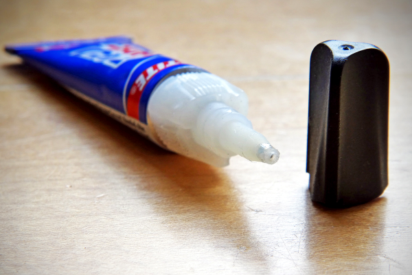
Many inventions happen not by design but through failure. They don’t happen through the failure directly, but because someone was paying attention and remembered the how and why of the failure, and learns from this. One of these inventions is Super Glue, the adhesive that every tinkerer and engineer has to hand to stick pretty much anything to anything, quickly. Although it was a complete failure for the original uses it was developed for, a chemist with good memory and an eye for a helpful product created it in a process he described as “one day of synchronicity and ten years of hard work.”
Super Glue was initially invented in 1942, when the chemist Harry Coover was working on a team trying to develop a clear plastic gun sight that would be cheaper than the metal ones already in use. The team cast a wide net, trying a range of new materials. Coover was testing a class of chemicals called cyanoacrylates. They had some promise, but they had one problem: they stuck to pretty much everything. Every time that Coover tried to use the material to cast a gun sight, it stuck to the container and was really hard to remove.
When the samples he tried came into contact with water, even water vapor in the air, they immediately formed an incredibly resilient bond with most materials. That made them lousy manufacturing materials, so he put the cyanoacrylates aside when the contract was canceled. His employer B. F. Goodrich, patented the process of making cyanoacrylates in 1947, but didn’t note any particular uses for the materials: they were simply a curiosity.
It wasn’t until 1951 when Coover, now at Eastman Kodak, remembered the sticky properties of cyanoacrylates. He and his colleague Fred Joyner were working on making heat-resistant canopies for the new generation of jet fighters, and they considered using these sticky chemicals as adhesives in the manufacturing process. According to Coover, he told Joyner about the materials and asked him to measure the refractive index to see if they might be suitable for use. He warned him to be careful, as the material would probably stick in the refractometer and damage it. Joyner tested the material and found it wasn’t suitable for a canopy but then went around the lab using it to stick things together. The two realized it could make an excellent adhesive for home and engineering use. Continue reading “Tech In Plain Sight: Super Glue” →
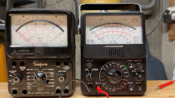
 Thankfully, in modern-day Western climates and with modern tech, you are not likely to encounter ESD-caused problems, but they were way more prominent back in the day. For instance, older hackers will have stories of how FETs were more sensitive, and touching the gate pin mindlessly could kill the FET you’re working with. Now, we’ve fixed this problem, in large part because we have added ESD-protective diodes inside the active components most affected.