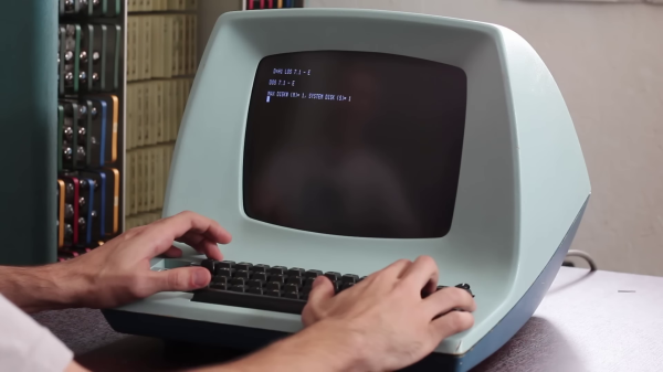
These days, data is as likely as not to be “in the cloud.” Otherwise, it’s probably on a USB flash drive or SD card. But in the old days, paper tape was a widespread way to store and retrieve data. A common way to start the day at the office was to toggle in a few dozen bytes of bootloader code, thread a bigger bootloader tape into your TeleType paper tape reader, and then get your coffee while the more capable bootloader clunked its way into memory. Then you could finish your brew while loading the tape with your compiler or whatever you wanted. [Scott Baker] has a Heathkit H8 and decided using a paper tape machine with it and some of his other gear would be fun.
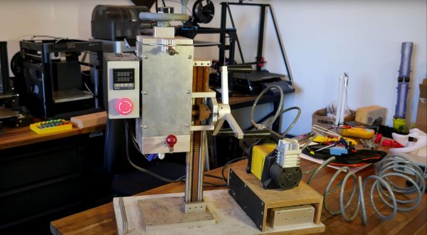
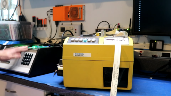
Instead of a TeleType, [Scott] picked up a used paper tape machine from FANUC intended for the CNC industry. They are widely available on the surplus market, although a working machine might run you $500. [Scott] paid $200, so he had some work to do to make the unit operational.
Paper tape had a few varieties. For computer work, you usually had a tape that could hold eight holes across, one for each bit in a byte. However, there are also 6-bit and 5-bit tapes for special purposes or different encodings (old TeleTypes used 5-bit characters in Baudot). The paper choice varied too. You could get plain paper, oiled paper, which maybe didn’t jam as often, and Mylar, which is less likely to shred up when it does jam.
To make things even more difficult, the machines all worked a little differently as well. Sure, punches almost all use solenoids. But the tape transport was sometimes a pinch roller and sometimes a sprocket-style drive. Reading the holes could be done with mechanical contacts or optically. Some punches left little “hanging chads” on the tape, so you didn’t have to empty a confetti box to throw away the chad.
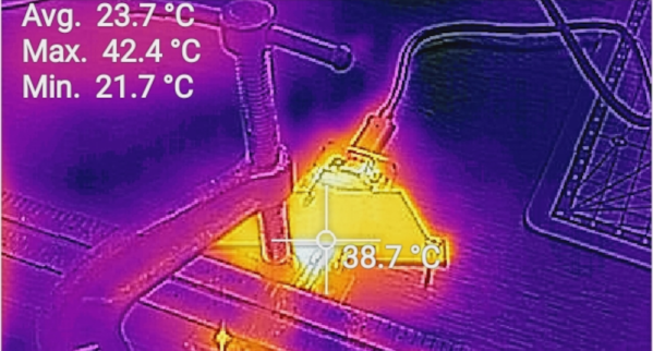
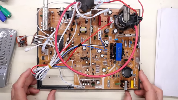
The repair job was interesting. Inside the machine is an 8051 microcontroller. There was no clock, and the circuit used two custom modules. One was simply a crystal, and the other was an oscillator. Removing both allowed a modern can oscillator to replace both modules. The next problem was a fried serial output driver. Replacing that got things working except for random resets due to a faulty brown-out reset circuit. That was easy to fix, too.
Of course, if you are really cheap, it is easy to make a paper tape reader from 8 phototransistors, and pulling tape through by hand isn’t unheard of. It can even talk USB. We’ve even seen a conference badge that can read tapes.
Continue reading “Let’s Listen To A Tape — Paper Tape” →