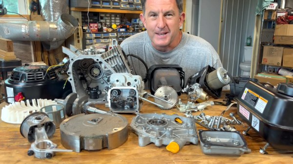
When the 6.5 HP (212 cc) Harbor Freight Predator engine in his kid’s go-kart gave up the ghost after some particularly hard driving, [HowToLou] figured it would be a good time to poke around inside the low-cost powerplant for our viewing pleasure. As a bonus, he even got it up and running again.
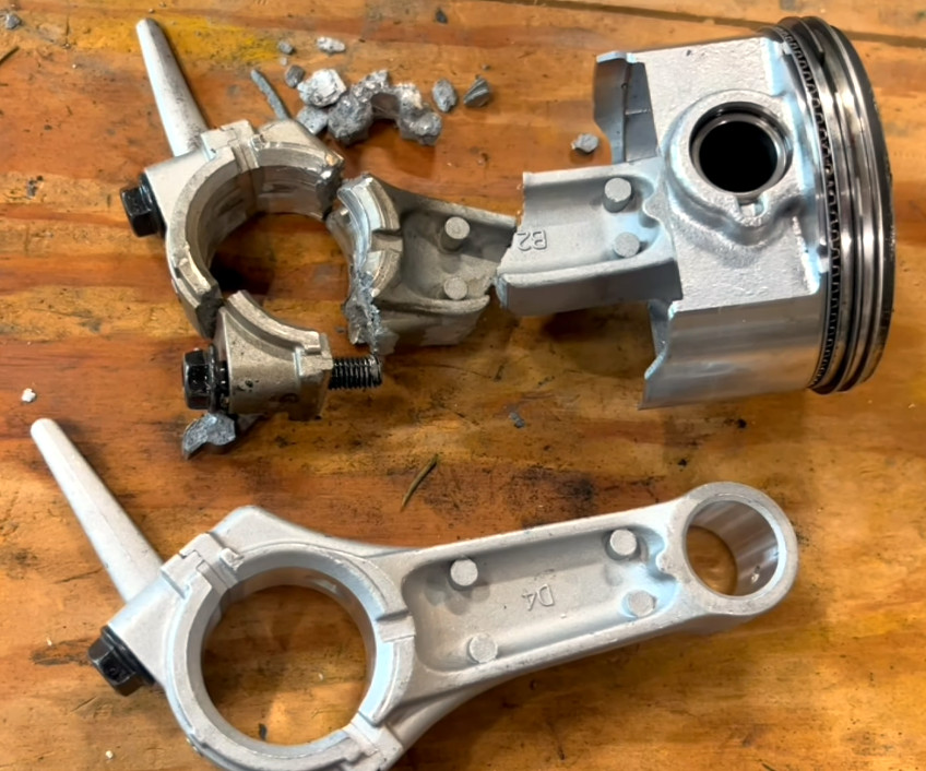
For an engine that has a retail price of just $160 USD, we’ve got to admit, the inside of the Predator doesn’t look too shabby. Admittedly, [HowToLou] determined that the cause of the failure was a blown connecting rod, but he also mentions that somebody had previously removed the engine’s governor, allowing it to rev up far beyond the nominal maximum of 3,600 RPM. No word on who snuck in there and yanked the governor out, but we’re betting it wasn’t the 7-year old driver…
Replacing the connecting rod meant taking most of the engine apart, but for our education, [HowToLou] decided to take it a bit further and remove everything from the engine. After stripping it down to the block, he re-installs each piece while explaining its function. If you’ve ever wanted to see what makes one of these little engines tick, or perhaps you’ve got a Predator 212 cc in need of a repair or rebuild, the presentation is a fantastic resource.
Incidentally, this isn’t the first time we’ve seen the go-kart in question — back in June, we covered the unique electric reverse that [HowToLou] came up with for it.

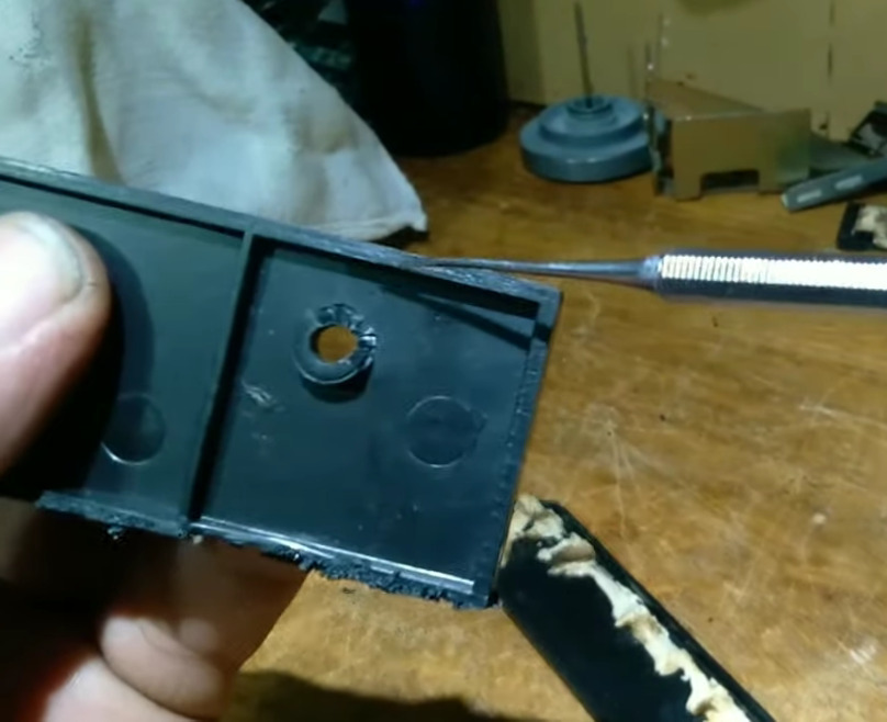


 The soft touch layer on the back didn’t go away with help of alcohol, but by sheer luck, an acetone bottle was nearby, and an acetone scrub helped get rid of the unpleasant stickiness. The tablet’s charging circuitry turned out to be unsophisticated – the tablet wouldn’t boot from MicroUSB input, and [Jonathan] wired up 5 volts from a USB cable straight into the battery input. Mind you, this might not be advised, as Lithium-Ion battery range is from 3 volts to 4.2 volts and a regulator would be called for, but [Jonatron] says it’s been working just fine.


