640k Was Never Enough For Anyone: How DOS Broke Free

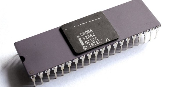
On modern desktop and laptop computers, there is rarely a need to think about memory. We all have many gigabytes of the stuff, and it’s just there. Our operating system does the heavy lifting of working out what goes where and what needs to be paged to disk, and we just get on with reading Hackaday, that noblest of computing pursuits. This was not always the case though, and for early PCs in particular the limitations of the 8086 processor gave the need for some significant gymnastics in search of an extra few kilobytes. [Julio Merion] has an interesting run-down of the DOS memory map, and how memory expansion happened on computers physically unable to see much of it.

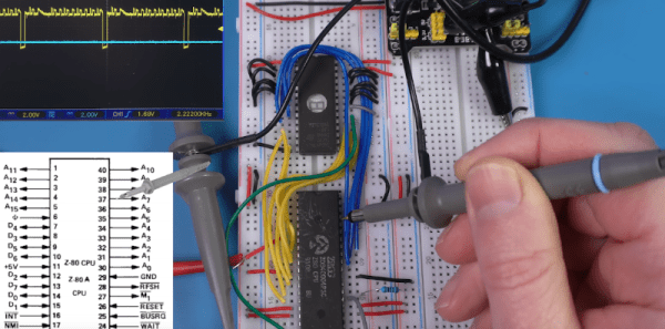
The 8086 has a 20-bit address bus, giving it access to a maximum of 1 megabyte. When IBM made the PC they needed space for the BIOS, the display, and the various accessory ROMs intended to come with expansion cards. Thus they allocated a maximum 640k of the map for RAM, and many early machines shipped with much less than that. The quote from Bill Gates about 640k being enough for anyone is probably apocryphal, but it was pretty clear as the 1980s wore on that more would be needed. The post goes into how memory expansion worked, with a 64k page mapped to switchable RAM on a card, and touches on how DOS managed extended memory above 1 Mb on the later processors that supported it. We dimly remember there also being a device driver that would map the unused graphics memory as EMS when the graphics card was running in text mode, but such horrors are best left behind.

Of course, some of the tricks to boost RAM were nothing but snake oil.

8086 header: Thomas Nguyen, CC BY-SA 4.0

Erasing EEPROMs Isn’t Always As Easy As It Seems

When is 14 volts not actually 14 volts? Given [Anders Nielsen]’s recent struggles with erasing an old-school EEPROM, it’s when you really need it that things tend to go pear-shaped.

A little background is perhaps in order. [Anders] is working on a scratch-built programmer for ROMs to complement his 65uino project, which puts a complete 6502 computer into the footprint of an Arduino Uno. He wisely started the ROM programmer project at the beginning, which was to generate the correct voltages for programming. This turned out to be not as easy as you might think thanks to the solderless breadboard’s parasitic effects on the MIC2288 switching boost regulator he chose.

The video below is a continuation of the programmer build, which ends up being just as fraught as the first part. Being able to generate the programming voltages is one thing; getting them onto the right pins at the right time using nothing but the 5-volt GPIOs on a microcontroller is another. In true retro fashion, [Anders] tackled that problem with a pair of small-signal transistors, which seemed to work once the resistor values were sorted, at least when applying a 12-volt signal intended to show the ROM’s hard-coded manufacturer ID on the data bus.

But erasing the ROM, which requires 14 volts while the chip enable line is held high for 100 ms, proved a little trickier. Despite multiple tries, the ROM wouldn’t erase thanks to the 14-volt rail being dragged down to around 9 volts. [Anders] fixed that with a new base resistor on the driver, to increase the current and keep the voltage up where it needs to be. Just goes to show you that the data sheets don’t always tell the whole story.

We’ve been enjoying the unfolding story of this programmer, and we’re looking forward to the next installment.

Continue reading “Erasing EEPROMs Isn’t Always As Easy As It Seems”

Z80 I/O Madness

While the 8080 started the personal computer revolution, the Z80 was quickly a winner because it was easier to use and had more capabilities. [Noel] found out though that the Z80 OUT instruction is a little odd and, in fact, some of the period documentation was incorrect.

Many CPUs used memory-mapped I/O, but the 8080 and Z80 had dedicated I/O addressing pins and instructions so you could fill up the memory map with actual memory and still have some I/O devices. A quick look in the famous Zak’s book on Z80 programming indicates that an instruction like OUT (C),A would write the A register to the output device indicated by the BC register pair (even though the instruction only mentions C. However, [Noel] missed the note about the B register and saw in the Zilog documentation that it did. Since he didn’t read the note in the Zak’s book until later, he assumed it was a discrepancy. Therefore, he went to the silicon to get the correct answer.

Breadboarding a little Z80 system allowed him to look at the actual behavior of the instruction. However, he also didn’t appreciate the syntax of the assembly language statements. We’ve done enough Z80 assembly that none of it struck us as particularly crazy, especially since odd instruction mnemonics were the norm in those days.

Still, it was interesting to see him work through all the instructions. He then looks at how Amstrad used or abused the instructions to do something even stranger.

If you want to breadboard a minimal Z80 system, consider this one. If you enjoy abuse of the Z80 I/O system, you don’t want to miss this Z80 hack for “protected mode.”

Continue reading “Z80 I/O Madness”

Check Out This PDP-11 Running Unix With A Teletype Terminal

If you’ve spent a few years around Hackaday, you’ve probably seen or heard of the DEC PDP-11 before. It was one of the great machines of the minicomputer era, back when machines like the Apple ][ and the Commodore 64 weren’t even a gleam in their creator’s eyes. You’ve also probably heard of Unix, given that so many of us use Linux on the regular. Well, now you can see them both in action, as [HappyComputerGuy] fires up real Unix on a real PDP-11/73… with a real Teletype Model 33 to boot!

It’s a fascinating dive into the tech of yesteryear, with a rich dose of history to boot. It’s mindboggling to think that video terminals were once prohibitively expensive and that teletype printers were the norm for interacting with computers. The idea of interacting with a live machine via a printed page is alien, but it’s how things were done! We’re also treated to a lesson on how to boot the PDP-11 with 2.11BSD which is a hilariously manual process. It also takes a very long time. [HappyComputerGuy] then shows off the Teletype Model 33 rocking the banner command to great effect.

It’s awesome to see this hardware as it would really have been used back in its heyday. Computing really was different before the microcomputer format became mainstream. It’s not the only PDP-11 we’ve seen lately, either! Video after the break.

Continue reading “Check Out This PDP-11 Running Unix With A Teletype Terminal”

PDP-11 Trouble With A Ruthless Power Supply Issue

After [David Lovett] of [Usagi Electric] was donated a few cars full of DEC PDP-11 minicomputers of various flavors and vintages, he passed on most of them to loving homes, but kept a few of them himself. One goal of this being to put together a PDP-11 system that could be more easily taken to vintage computer shows than the ‘rollable’ PDP-11s he had access to prior. Of 1980s PDP-11s, the first-generation Large Scale Integration (LSI) PDP11/03 system (so-called Q-Bus models) is among the smallest, taking up about as much space as a 1980s desktop PC, while supporting the second generation LSI PDP-11/23 cards. It all seemed so easy until [David] tried testing the PDP-11/03’s PSU and everything went south.

Despite having access to the circuit diagrams of the PSU, figuring out what was going wrong was an absolute nightmare for [David], after some easy fixes involving replacing a blown fuse and bulging capacitors failed to deliver salvation. Reading through the comments to the video, it would seem that people are generally confused about whether this PSU is a linear, switching or some other configuration. What is clear is that with the absolutely massive transformer, it looks more like a linear power supply, but with a lot of protections against over current and other failure modes built-in, all of which rely on transistors and other components that could have gone bad.

Although in round 1 the PDP-11/03 PSU won the battle, we hope that once round 2 commences [David] will have had the proverbial training montage behind him (set to ‘Eye of the Usagi’, probably) and will manage to get this PSU working once more.

Continue reading “PDP-11 Trouble With A Ruthless Power Supply Issue”

Wiring An SD Card To A Handspring PDA’s 68K Bus With Only Three SOT23s

In 1998 the founders of Palm had a bit of a falling out with the wildly successful PDA company’s new owners. They set up a new company called Handspring, which enabled them to make PDAs again in the way they preferred, This resulted in the Handspring Visor line of PDAs, which featured a big cartridge slot called the Springboard Expansion slot. Much like a Gameboy, you could put in a range of modules, ranging from games to cameras to memory expansion and more. Since these modules connect directly to the internal Motorola 68k-based microprocessor, you could make a module either to comply with this standard or if you’re like [Dmitry], you’d figure out a way to get an SPI device like an SD card to communicate and expand storage.

Editor note: Dmitry’s design isn’t the first SD/MMC interface for the Visor. Portable Innovation Technology’s SD MemPlug Module supported SD/MMC way back in 2002. However – MemPlug was a commercial product, while Dmitry’s work is open source.

Continue reading “Wiring An SD Card To A Handspring PDA’s 68K Bus With Only Three SOT23s”

TMS 1000 Microcontroller - By Antonio Martí Campoy - Own work, CC BY-SA 4.0

The Early History Of The Microcontroller: It Came From Texas

Ti’s presentation of the rapid integration of calculator chips.

Although for most generations alive today the era of microcontrollers (MCU) feels like it starts somewhere with the Intel 8051 and AVR MCUs, the history of these self-contained computing marvels that are now found just about anywhere begins long before those were even conceptualized. In a recent article titled Tiny Computers From Texas, [Babbage] goes through this early history of what would ultimately become such an integral part of daily life.

An MCU is defined as a small, self-contained computer, which requires few to no external components to function. This contrasted with the more traditional MPUs, or microprocessor units, where a computer was assembled out of one or more MPUs, I/O chips, memory SRAM and so on. It’s perhaps little surprise that the drive towards MCUs was the result of primarily the calculator market, where competing firms were trying to upstage each other with higher levels of integration into as few chips as possible, while driving down costs and power usage.

Ultimately, the Texas Instruments TMS 1000 was the first true MCU that got produced in large volumes after its release in 1974. Moving beyond calculators, the TMS 1000 found its way into toys, including the Speak & Spell – which uses another Ti chip (TMS 5100) for the voice synthesis – so that today any toy can be interactive in exciting and often noisy ways.

Back in 2020 we took our own affectionate look at this chip.