There’s no question that Sony’s PlayStation Portable (PSP) was an impressive piece of hardware when it was released in 2004, but for all its technical wizardry, it wasn’t able to shake Nintendo’s vice-like grip on the handheld market. Perhaps that explains why we still see so many nostalgia-fueled hacks for Nintendo’s Game Boy and Dual Screen (DS) systems, while PSP hacks tend to be few and far between.
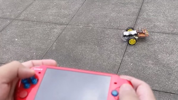
But looking at projects like this one that turn the PSP into a capable robot controller (video, embedded below) we can’t help but wonder if the community has been missing out. Thanks to an open source software development kit for the system, [iketsj] was able to write a WiFi controller program that can be run on any PSP with a homebrew-compatible firmware.
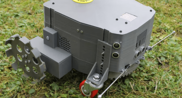
 The other side of the equation is a simple robot powered by an ESP8266. To take control of the bot, the user connects their handheld to the WiFi network being offered by the MCU and fires up the controller application from the main menu. It’s all very slick, and the fact that you don’t need to make any modifications to the PSP’s hardware is a huge plus. From the video after the break we get the impression that the remote software is pretty simplistic in its current form, but we imagine the only really limitations are how good you are at writing C code for what by today’s standards would be considered a fairly resource constrained system. We’d love to see that widescreen display lit up and showing live first-person video from the bot’s perspective.
Many of the PSP hack’s we’ve seen over the years have been about repurposing the hardware, or in some cases, replacing the system’s internals with something raspberry flavored. Those projects have certainly been interesting in their own ways, but we really like the idea of being able to push a largely stock system into a new role just by writing some custom code for it.
Continue reading “PSP Turned Robot Remote With Custom Software”