Scratch Built Tracked Robot Reporting For Duty

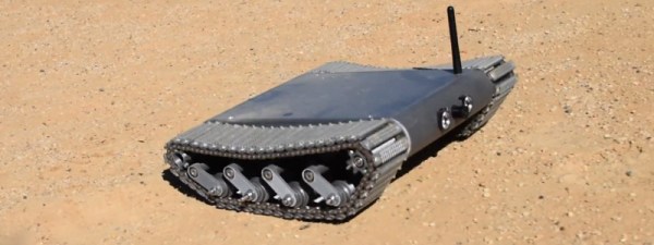
Inspired by battle-hardened military robots, [Engineering Juice] wanted to build his own remote controlled rover that could deliver live video from the front lines. But rather than use an off-the-shelf tracked robot chassis, he decided to design and 3D print the whole thing from scratch. While the final product might not be bullet proof, it certainly doesn’t seem to have any trouble traveling through sand and other rough terrain.

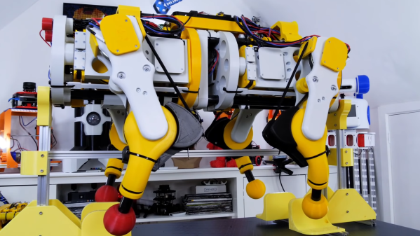
Certainly the most impressive aspect of this project is the roller chain track and suspension system, which consists of more than 200 individual printed parts, fasteners, bearings, and linkages. Initially, [Engineering Juice] came up with a less complex suspension system for the robot, but unfortunately it had a tendency to bind up during testing. However the new and improved design, which uses four articulated wheels on each side, provides an impressive balance between speed and off-road capability.

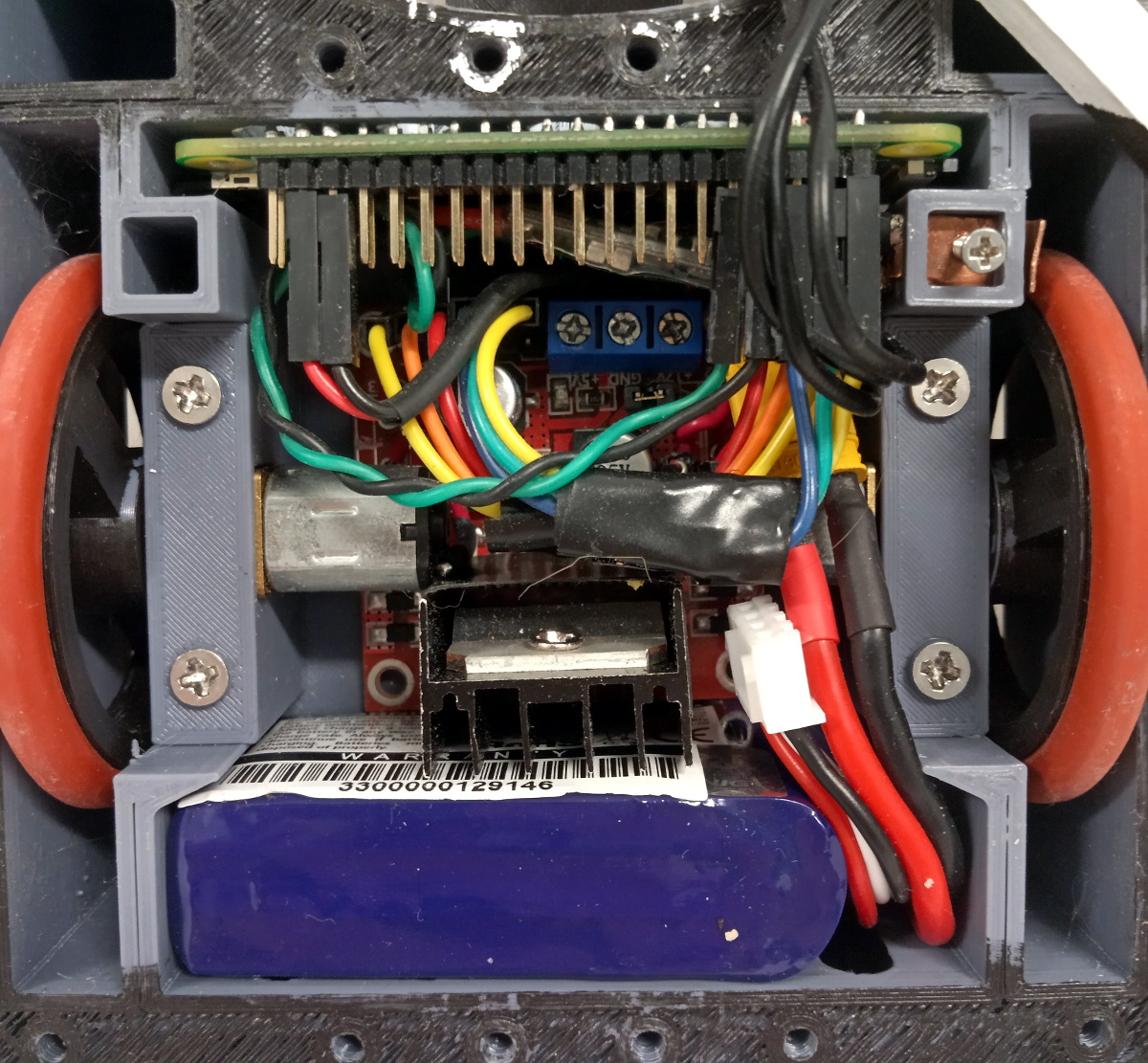
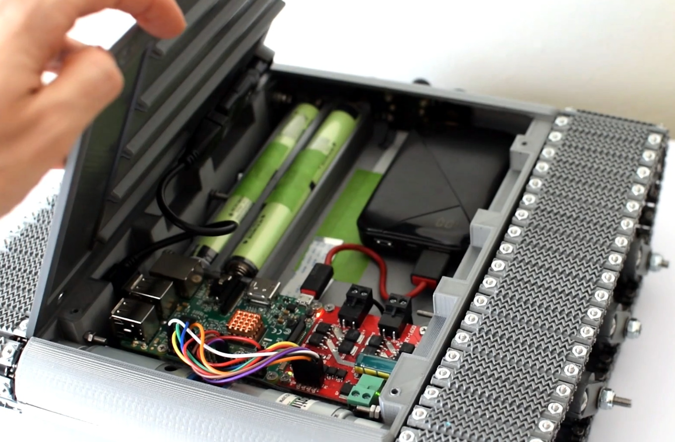
Internally there’s a Raspberry Pi 4 paired with an L298 dual H-bridge controller board to drive the heavy duty gear motors. While the Pi is running off of a standard USB power bank, the drive motors are supplied by a custom 18650 battery pack utilizing a 3D printed frame to protect and secure the cells. A commercial night vision camera solution that connects to the Pi’s CSI header is mounted in the front, with live video being broadcast back to the operator over WiFi.

To actually control the bot, [Engineering Juice] has come up with a Node-RED GUI that’s well suited to a smartphone’s touch screen. Of course with all the power and flexibility of the Raspberry Pi, you could come up with whatever sort of control scheme you wanted. Or perhaps even go all in and make it autonomous. It looks like there’s still plenty of space inside the robot for additional hardware and sensors, so we’re interested to see where things go from here.

Got a rover project in mind that doesn’t need the all-terrain capability offered by tracks? A couple of used “hoverboards” can easily be commandeered to create a surprisingly powerful wheeled platform to use as a base.

Continue reading “Scratch Built Tracked Robot Reporting For Duty”

Bungee And Cam Assisted Actuator For OpenDog

One of the challenges of many walking robot designs is the fact that they draw current just to stay upright. This was exactly the case for one [James Bruton]’s quadruped robots, where the knee motors were getting too hot to touch. Adding springs to take some of the load is not as simple it might seem, so [James] created a bungee assisted cam mechanism to do the job.

For a normal spring-loaded lever, force is proportional to how much the spring is stretched, which will require the actuators to draw more and more current as it lifts the leg higher. For the spring force to remain constant throughout the range of motion, the length of the lever arm must become continuously shorter as the knee is bent.  [James] did this by stretching a bungee cord around a cam. The added bulk of the cam does however cause the knees to knock into each other in some scenarios, but [James] plans to adjust the robot’s gait to avoid this. He didn’t get around to actually measuring the current draw reduction, but the motor temperature has dropped significantly, only being slightly warm after a test run.

These tests were done with OpenDog V2, but [James] is already working on the design of V3, which will use 3D printed cycloidal gearboxes. At the moment, that build is still being delayed thanks to the global component shortage. Continue reading “Bungee And Cam Assisted Actuator For OpenDog”

Raspberry Pi Zero Takes The Wheel In Miniature Fighting Robot

Looking to capitalize on his familiarity with the Raspberry Pi, [Sebastian Zen Tatum] decided to put the diminutive Pi Zero at the heart of his “antweight” fighting robot, $hmoney. While it sounds like there were a few bumps in the road early on, the tuxedoed bot took home awards from the recent Houston Mayhem 2021 competition, proving the year of Linux on the battle bot is truly upon us.

Compared to using traditional hobby-grade RC hardware, [Sebastian] says using the Pi represented a considerable cost savings. With Python and evdev, he was able to take input from a commercial Bluetooth game controller and translate it into commands for the GPIO-connected motor controllers. For younger competitors especially, this more familiar interface can be seen as an advantage over the classic RC transmitter.

A L298N board handles the two N20 gear motors that provide locomotion, while a Tarot TL300G ESC is responsible for spinning up the brushless motor attached to the “bow tie” spinner in the front. Add in a Turnigy 500mAh 3S battery pack, and you’ve got a compact and straightforward electronics package to nestle into the robot’s 3D printed chassis.

In a Reddit thread about $hmoney, [Sebastian] goes over some of the lessons his team has learned from competing with their one pound Linux bot. An overly ambitious armor design cost them big at an event in Oklahoma, but a tweaked chassis ended up making them much more competitive.

There was also a disappointing loss that the team believes was due to somebody in the audience attempting to pair their phone with the bot’s Pi Zero during the heat of battle, knocking out controls and leaving them dead in the water. Hopefully some improved software can patch that vulnerability before their next bout, especially since everyone that reads Hackaday now knows about it…

While battles between these small-scale bots might not have the same fire and fury of the televised matches, they’re an excellent way to get the next generation of hackers and engineers excited about building their own hardware. We wish [Sebastian] and $hmoney the best of luck, and look forward to hearing more of their war stories in the future.

Sand Hack Boosts Power On InSight Mars Lander

We love that part in Apollo 13 where the NASA engineers have to fit a square carbon dioxide filter in a round hole. We love basically every scene of The Martian where Mark Watney hacks together any piece of hardware he can get his hands on to survive on a hostile planet. What we love even more is watching actual NASA engineers trying out a hack and ordering the InSight lander to scoop sand on itself to increase the power from its solar panels.

InSight, which recently had its two-year mission to study the interior geology of Mars extended, has been suffering from a buildup of dust on its solar panels. This dust is only adding on to the expected power loss which occurs as the red planet approaches aphelion — the maximum distance from the Sun in its orbit. Attempts to shake the panels clear by pulsing their deployment motors were unsuccessful. Other solar-powered missions have experienced a cleaning effect from the Martian winds; however, despite seeing plenty of gusts, InSight has not seen any significant improvement.

Counterintuitively, operators instructed the lander to slowly trickle more dust and sand from its scoop close to (not on top of) one of the solar panels. As the wind blew, larger particles were carried by the breeze across the panels and bounced off the surface, carrying away some accumulated dust. While that may sound like a minuscule effect, the experiment resulted in about 30 extra watt-hours per Sol. Margins are still thin, and science instruments will still need to be disabled to conserve power. But this boost alone was enough to delay the powerdown for a few weeks.

There are so many exciting missions operating on Mars right now. Though, it’s also fun to take a look back at some of the earliest probes. And we’re always amazed at the resources NASA makes available for us to have some DIY fun.

Robot Clings To Ceiling

Imagine you are at the movies and you see a Roomba-like robot climbing a wall or clinging to a ceiling. How would that work? If you are like us, you might think of suction cups or something mechanical or magnetic in the wall. Then again, it is a movie, so maybe it is just a camera trick. The robots from the Bioinsipired Robotics and Design Lab at UCSD are no camera trick, though. As [Evan Ackerman] mentions in a post on IEEE Spectrum, “It’s either some obscure fluid effect or black magic.” You can watch a video about the bots, below.

It turns out, the answer is closer to a suction cup than you might think. According to the paper from the lab, a small flexible disk vibrates at 200 Hz. This generates a thin (less than 1 mm) layer of low pressure air in between the disk and the underlying surface. The robot can resist a force of up to 5 newtons from the suction from the disk.

Continue reading “Robot Clings To Ceiling”

3D-Printed Scale Model Of Perseverance Rover Seems As Complicated As The Real One

Sometimes the best way to figure out how something works is to make a model of it. 3D-modeling software makes it possible to do the job in silico, and sometimes that’s enough. But to really get inside the designer’s head, executing a physical model, like this quarter-scale RC-controlled Perseverance rover, is a great way to go.

If you’re looking for cutting-edge tech or groundbreaking design, this build will probably not light your fire. But a closer look will show not only great details about how JPL designs robots that can operate on Mars, but some great design and 3D-printing tips too. [Dejan]’s modeling process started with the 3D renderings of Perseverance available on the NASA website, which went into SolidWorks via Blender. [Dejan] was intent on capturing all the details of the rover, even those that ended up just for looks. But there’s plenty of functionality, too — the running gear looks and functions just like the six-wheel double-bogie design used on Perseverance, as well as Curiosity before it. This revealed an interesting fact that we didn’t previously realize — that the hull is suspended from a single pivot point on each side, while a linkage across the deck both prevents the body from pivoting and provides differential control of the drive bogies on either side of the rover.

The video below shows both the impressive amount of 3D printing needed to make all the model’s parts as well as the involved assembly process. It also shows the Arduino-controlled model being piloted around via radio control. There’s a lot to learn from this model, and [Dejan]’s craftsmanship here is top-notch too. We’ve seen such builds before from him, like this 3D-printed SCARA arm, a CNC hot-wire foam cutter, and an automated wire bender.

Continue reading “3D-Printed Scale Model Of Perseverance Rover Seems As Complicated As The Real One”

Tiny PCB Motor Robot Is Making Its First Wobbly Moves

[Carl Bugeja] has been working on his PCB motors for more than three years now, and it doesn’t seem like he is close to running out of ideas for the project. His latest creation is a tiny Bluetooth-controlled robot built around two of these motors.

One of the main challenges of these axial flux PCB motors is their low torque output, so [Carl] had to make the robot as light as possible. The main board contains a microcontroller module with integrated Bluetooth, an IMU, regulator, and two motor drivers. The motor stator boards are soldered to the main board using 90° header pins. The frame for the body and the rotors for the motors are 3D printed. A set of four neodymium magnets and a bearing is press-fit into each rotor. The motor shafts are off-the-shelf PCB pins with one end soldered to the stator board. Power comes from a small single-cell lipo battery attached to the main board.

The robot moves, but with a jerking motion, and keeps making unintended turns. The primary cause of this seems to be the wobbly rotors, which mean that the output torque fluctuates throughout the rotation of the motor. Since there are only two points of contact to the ground, only the weight of the board and battery is preventing the central part from rotating with the motors. This doesn’t look like it’s quite enough, so [Carl] wants to experiment with using the IMU to smooth out the motion. For the next version, he’s also working on a new shaft mount, a metal rotor, and a more efficient motor design.

We look forward to seeing this in action, and also what other application [Carl] can come up with. He has already experimented with turning it into a stepper motor, a linear motor, and a tiny jigsaw motor.

Continue reading “Tiny PCB Motor Robot Is Making Its First Wobbly Moves”