Hackaday is primarily a place for electronics hackers, but that’s not to say that we don’t see a fair number of projects where woodworking plays a key role. Magic mirror builds come to mind, as do restorations of antique radios, arcade machines built into coffee tables, and small cases for all manner of electronic and mechanical gadgets. In some of these projects, the woodworking really shines and makes the finished project pop. In others — well, let’s just say that some woodwork looks good from far, but is far from good.
In the almost five years since the launch of the original Raspberry Pi we have seen a huge array of competitors emerge in the inexpensive single board computer market. Many have created their own form factors, but an increasing number have gone straight for the jugular of the fruity board from Cambridge by copying its form factor and interfaces as closely as possible. We’ve seen sterling efforts from the likes of Banana Pi, Odroid, and several others, but none have yet succeeded in toppling it from its pedestal.
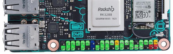
The ASUS Tinker specification.
The latest contender in this arena might just make more of an impact though, because it comes from a major manufacturer, a name you will have heard of. Asus have quietly released their Tinker, board that follows the Pi form factor very closely, and packs a 1.8 GHz quad-core ARM Cortex A17 alongside an impressive spec we’ve captured as an image for this article. Though they are reticent about it on their website, there is a SlideShare presentation with some of the details, which we’ve placed below the break.
At £55 (about $68) where this is being written it’s more expensive than the Pi, but Asus go to great lengths to demonstrate that it is significantly faster. We will no doubt verify the accuracy of that claim as the boards find their way into the hands of our community. Still, it features a mostly-Pi-compatible I/O header, and the same display and camera connectors as the Pi. There is no information as to how compatible these last two are though.
Other boards in this arena have boasted impressive hardware, but have fallen down when it comes to the support for their operating systems. When you buy a Raspberry Pi it is not just the hardware you are taking on but the Raspbian operating system and its impressive community support. The Tinker supports Debian, so if Asus is to make a mark they must ensure that its support rivals that of the board it is targeting. If they succeed in that endeavor then the result can only be good news for us.
Recharging your mobile phone or your electric vehicle in a few minutes sure sounds appealing. Supercapacitor technology has the potential to deliver that kind of performance that batteries currently can’t, and while batteries are constantly improving, the pace of development is not very fast. Just remember your old Nokia mobile with Ni-Cad batteries and several days of usage before a recharge was needed. Today we have Lithium-Ion batteries and we have to charge our phones every single day. A better energy storage option is clearly needed, and supercapacitors seem to be the only technology that is close to replace the battery.
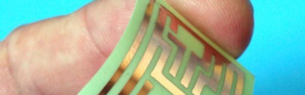
Let’s get it out of the way right up front: you still need to etch the boards. However, [Mikey77] found that flexible plastic (Ninjaflex) will adhere to a bare copper board if the initial layer height is set just right. By printing on a thin piece of copper or conductive fabric, a resist layer forms. After that, it is just simple etching to create a PCB. [Mikey77] used ferric chloride, but other etchants ought to work, as well.
Sound simple, but as usual, the devil is in the details. [Mikey77] found that for some reason white Ninjaflex stuck best. The PCB has to be stuck totally flat to the bed, and he uses spray adhesive to do that. Just printing with flexible filament can be a challenge. You need a totally constrained filament path, for one thing.
When we see a new build by [Gord] from Gord’s Garage, we never know what to expect. He seems to be pretty skilled at whatever he puts his hand to, with a great design sense and impeccable craftsmanship. You might expect him to tone it down a little for a STEM-outreach wind turbine project then, but when you get a chance to impress 28 fifth and sixth graders, you might as well go for it.
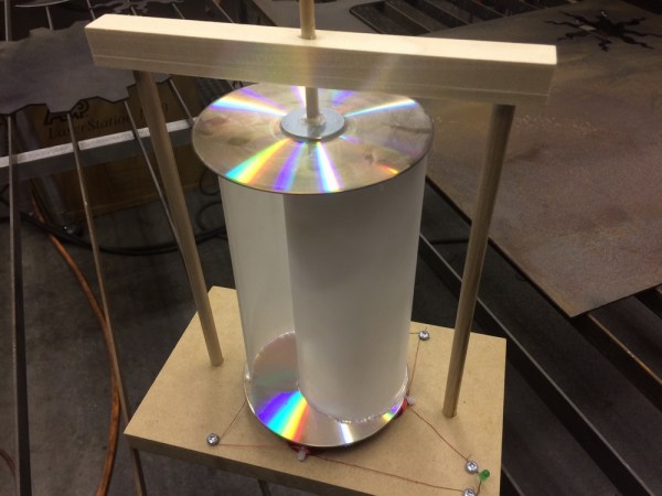
Starting with an idea from his daughter’s teacher for wind turbines each kid could make, [Gord] applied a little lean methodology so the kids would be able to complete the build in the allotted time. The design is simple – a couple of old CDs holding vertical sections of PVC tubing to catch the breeze and spin neodymium magnets over four flat coils of magnet wire. It’s enough to light a single LED and perhaps a kid’s imagination.
As simple as the turbine is, the process of building it needed to be stripped of as much unnecessary work as possible, and [Gord] really shines here. He built jigs and fixtures galore, pre-built some assemblies, and set up well-organized workstations for each step of the build. Everything was clearly labeled, adult volunteers were trained using the video after the break, and a good time was had by all.
Sometimes the hack isn’t in the product but in the process, and [Gord] managed to hack a success out a potential disaster of disappointed kids. If getting a taste of [Gord]’s style makes you want to see more, check out his guitar fretting jig or his brake rotor mancave clock.
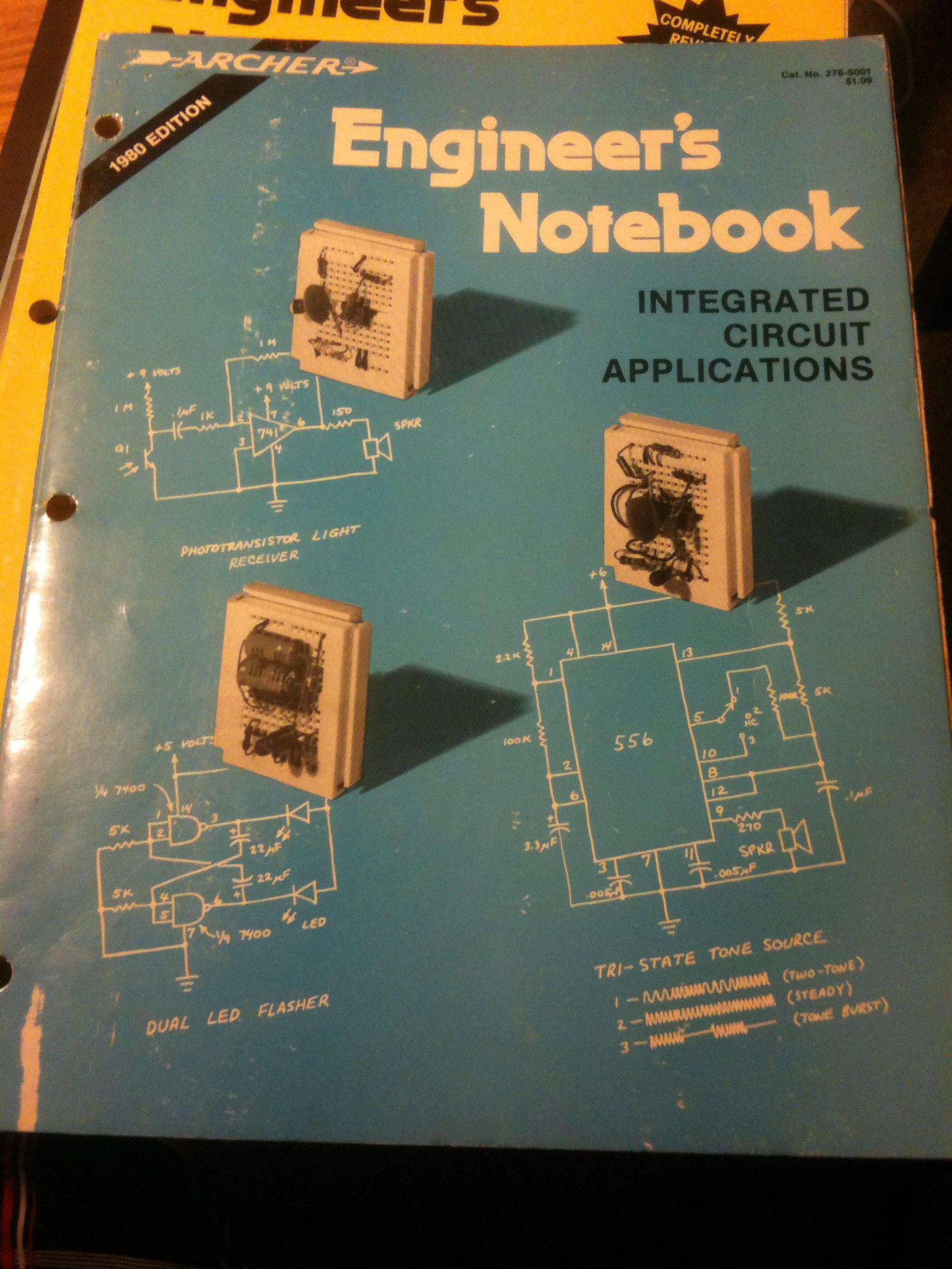
There was a time when Radio Shack offered an incredible variety of supplies for the electronics hobbyist. In the back of each store, past the displays of Realistic 8-track players, Minimus-7 speakers, Patrolman scanners, and just beyond the battery bin where you could cash in your “Battery of the Month Club” card for a fresh, free 9-volt battery, lay the holy of holies — the parts. Perfboard panels on hinges held pegs with cards of resistors for 49 cents, blister packs of 2N2222 transistors and electrolytic capacitors, and everything else you needed to get your project going. It was a treasure trove to a budding hardware hobbyist.
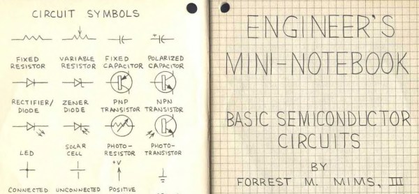
But over on the side, invariably near the parts, was a rack of books for sale, mostly under the Archer brand. 12-year old me only had Christmas and birthday money to spend, and what I could beg from my parents, so I tended to buy books — I figured I needed to learn before I started blowing money on parts. And like many of that vintage, one of the first books I picked up was the Engineer’s Notebook by Forrest M. Mims III.
Wish I could find my original copy from 1979. I just bought this one from Amazon.
Many years rolled by, and my trusty and shop-worn first edition of Mims’ book, with my marginal notes and more than one soldering iron burn scarring its pulp pages, has long since gone missing. I learned so much from that book, and as I used it to plan my Next Big Project I’d often wonder how the book came about. Those of you that have seen the book and any of its sequels, like the Mini-notebook Series, will no doubt remember the style of the book. Printed on subdued graph paper with simple line drawings and schematics, the accompanying text did not appear to be typeset, but rather hand lettered. Each page was a work of technical beauty that served as an inspiration as I filled my own graph-paper notebooks with page after page of circuits I would find neither the time nor money to build.
I always wondered about those books and how they came about. It was a pretty astute marketing decision by Radio Shack to publish them and feature them so prominently near the parts — sort of makes the string of poor business decisions that led to the greatly diminished “RadioShack” stores of today all the more puzzling. Luckily, Forrest Mims recently did an AMA on reddit, and he answered a lot of questions regarding how these books came about. The full AMA is worth a read, but here’s the short story of those classics of pulp non-fiction.
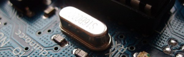
Accurate timing is one of the most basic requirements for so much of the technology we take for granted, yet how many of us pause to consider the component that enables us to have it? The quartz crystal is our go-to standard when we need an affordable, known, and stable clock frequency for our microprocessors and other digital circuits. Perhaps it’s time we took a closer look at it.
The first electronic oscillators at radio frequencies relied on the electrical properties of tuned circuits featuring inductors and capacitors to keep them on-frequency. Tuned circuits are cheap and easy to produce, however their frequency stability is extremely affected by external factors such as temperature and vibration. Thus an RF oscillator using a tuned circuit can drift by many kHz over the period of its operation, and its timing can not be relied upon. Long before accurate timing was needed for computers, the radio transmitters of the 1920s and 1930s needed to stay on frequency, and considerable effort had to be maintained to keep a tuned-circuit transmitter on-target. The quartz crystal was waiting to swoop in and save us this effort.