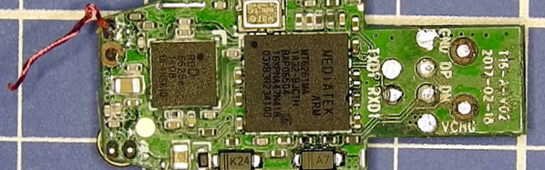
[Mitch] got interested in the S8 “data line locator” so he did the work to tear into its hardware and software. If you haven’t seen these, they appear to be a USB cable. However, inside the USB plug is a small GSM radio that allows you to query the device for its location, listen on a tiny microphone, or even have it call you back when it hears something. The idea is that you plug the cable into your car charger and a thief would never know it was a tracking device. Of course, you can probably think of less savory uses despite the warning on Banggood:
Please strictly abide by the relevant laws of the state, shall not be used for any illegal use of this product, the consequences of the use of self conceit.
We aren’t sure what the last part means, but we are pretty sure people can and will use these for no good, so it is interesting to see what they contain.
When writing a recent piece about Reverse Polish Notation, or RPN, as a hook for my writing I retrieved my Sinclair Scientific calculator from storage. This was an important model in the genesis of the scientific calculator, not for being either a trailblazer or even for being especially good, but for the interesting manner of its operation and that it was one of the first scientific calculators at an affordable price.
I bought the calculator in a 1980s rummage sale, bodged its broken battery clip to bring it to life, and had it on my bench for a few years. Even in the early 1990s (and even if you didn’t use it), having a retro calculator on your bench gave you a bit of street cred. But then as life moved around me it went into that storage box, and until the RPN article that’s where it stayed. Finding it was a significant task, to locate something about the size of a candy bar in the storage box it had inhabited for two decades, among a slightly chaotic brace of shelves full of similar boxes.
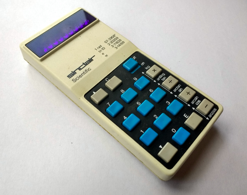
The Sinclair’s clean design still looks good four decades later.
Looking at it though as an adult, it becomes obvious that this is an interesting machine in its own right, and one that deserves a closer examination. What follows will not be the only teardown of a Sinclair Scientific on the web, after all nobody could match [Ken Shirriff]’s examination of the internals of its chip, but it should provide an insight into the calculator’s construction, and plenty of satisfying pictures for lovers of 1970s consumer electronics.
The Sinclair is protected by a rigid black plastic case, meaning that it has survived the decades well. On the inside of the case is a crib sheet for its RPN syntax and scientific functions, an invaluable aid when it comes to performing any calculations.
It shares the same external design as the earlier Sinclair Cambridge, a more humble arithmetic calculator, but where the Cambridge’s plastic is black, on the Scientific it is white. The LED display sits behind a purple-tinted window, and the blue-and-black keyboard occupies the lower two-thirds of the front panel. At 50 x 111 x 16 mm it is a true pocket calculator, with an elegance many of its contemporaries failed to achieve and which is certainly not matched by most recent calculators. Good industrial design does not age, and while the Sinclair’s design makes it visibly a product of the early 1970s space-age aesthetic it is nevertheless an attractive item in its own right.
Hardware teardowns are awesome when guided by experts. One of our favorites over the years has been [Mike Harrison], who has conquered teardowns of some incredibly rare and exquisitely engineered gear, sharing the adventure on his YouTube channel: mikeselectricstuff. Now he’s putting on a workshop to walk through some of the techniques he uses when looking at equipment for the first time.
[Mike] will be in Pasadena a few days early for the Hackaday Superconference and floated the idea of hosting a workshop. We ordered up some interesting gear which he hasn’t had a chance to look at yet. A dozen lucky workshop attendees will walk through the process [Mike] uses to explore the manufacturing and design choices — skills that will translate to examining any piece of unknown gear. He may even delve into the functionality of the equipment if time allows. Get your ticket right now!
To keep things interesting we’re not going to reveal the equipment until after the fact. But follow the event page where we’ll publish the details of his reverse engineering work after the workshop.
[Mike] is the badge designer for this year’s Hackaday Superconference badge. Unfortunately Supercon is completely sold out (we tried to warn you) but you can check out the badge details he already published. And we will be live streaming the Supercon this year — more details on that next week!
A few weeks ago I needed a power strip in my home office. The outlet in question is located behind a filing cabinet so it would need a low profile plug. I jumped on Amazon to buy a surge suppressor strip. That’s when I noticed strips with rotating plugs. I’ve always had some apprehensions about plugs like that, though I could never quite put my finger on why. Looking at the reviews on this particular plug, I found some scary issues. Photos of melted plugs, melted outlets, and cries of “fire hazard”. So I did what any crazy hacker would do – bought two power strips. One with a fixed right angle plug to use in my office, and one with a rotating plug to tear down.
Failed plug – from Amazon reviews
Surge suppressors, power strips, outlet strips, they have many names. Underwriter’s Laboratories (UL) calls them “Relocatable power taps”. They all have several outlets, most have a circuit breaker of some sort inside, and some have circuits for surge suppression. These are some of the most common devices to find in the modern home. Many of our houses were designed and built before surround sound, cable boxes, computers, modems, cell phone chargers, tablet chargers, and all our other modern conveniences. There weren’t as many electrical loads, so the houses didn’t have many outlets. Power strips solve this problem.
After a couple of days, I had my strips in hand. I expected the plug to rotate once – maybe 270 degrees. That would indicate there were wires connecting the rotating head to rest of the plug. Not so – this plug would spin round and round all day long.
It is hard to remember now, but there was a time when electronics were expensive. [Adrian Black] found some 9W (60W equivalent) LED light bulbs at the Dollar Tree (a U.S. store where everything costs a dollar). Naturally, they cost a dollar, and he wanted to see what was inside of them. You can see the resulting video, below.
Apparently where [Adrian] lives there is a subsidy paid to retailers for selling LED lighting, so you may not be able to get the same bulbs at that price. Still, the price of these bulbs has dropped like a rock over the last few years.
Oscillators with components that aren’t electrically connected to anything? PCB traces that function as passive components based solely on their shape? Slots and holes in the board with specific functions? Welcome to the weird and wonderful world of microwave electronics, brought to you through this teardown and analysis of a Doppler microwave transceiver module.
We’ve always been fascinated by the way conventional electronic rules break down as frequency increases. The Doppler module that [Kerry Wong] chose to pop open, a Microsemi X-band transceiver that goes for about $10 on eBay right now, has vanishingly few components inside. One transistor for the local oscillator, one for the mixer, and about three other passives are the whole BOM. That the LO is tuned by a barium titanate slug that acts as a dielectric resonator is just fascinating, as is the fact that PB traces can form a complete filter network just by virtue of their size and shape. Antennas that are coupled to the transceiver through an air gap via slots in the board are a neat trick too.
[Kerry] analyzes all this in the video below and shows how the module can be used as a sensor. If you need a little more detail on putting these modules to work, we’ve got some basic circuits you can check out.
Levitating chairs from the Jetsons still have a few years of becoming a commercial product though they are fun to think about. One such curious inventor, [Conor Patrick], took a deep dive into the world of maglev and came up with a plan to create a clock with levitating hands. He shares the first part of his journey to horizontal levitational control.
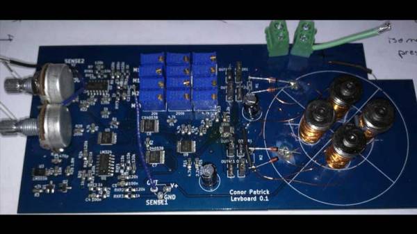
[Conor Patrick] bought an off-the-shelf levitation product that was capable of horizontal levitation. Upon dissecting it he found a large magnet, four electromagnet coils, and a hall effect sensor. These parts collectively form a closed-loop control to hold an object at a specific distance. He soon discovered that in fact, there were just two coils energized by H-bridges. His first attempt at replicating the circuit, he employed a breadboard which worked fine for a single axis model. Unfortunately, it did not work as expected with multiple coils.
After a few iteration and experiments with the PID control loop, he was able to remove unwanted sensor feedback as well as overshoot in control current. He finally moved to a Teensy with a digital PD loop. The system works, but only marginally. [Conor Patrick] is seeking help from the control loop experts out there and that is the essence of the OSHW world. The best part of this project is that it is a journey that involves solving one problem at a time. We hope to see some unique results in the future.
We have covered Acoustic Levitation in the past and the Levitating Clock on a similar beat. We’re certain a more refined approach is on the horizon since many of us are now looking at making one to experiment with on our workbench.