We always look forward to the builds [MakerMan] sends in, and it’s not just because we dig his choices in royalty free music (though it helps). He always manages to put together his projects with a minimum of fuss, and perhaps more importantly, a minimum of funds. His builds use salvaged components, easily sourced materials, and common tools. Watching him work invariably makes us realize that we tend to overthink our own projects.
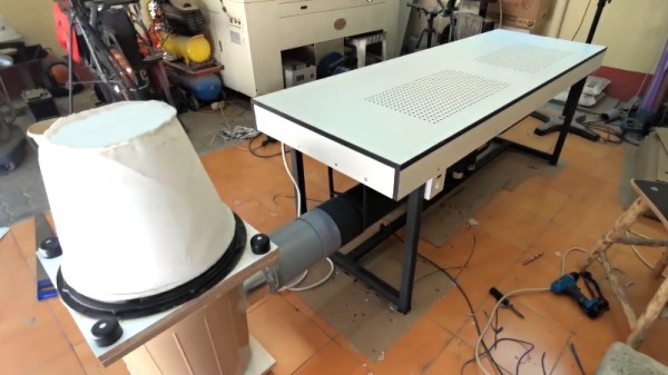
 In his latest video, [MakerMan] was tasked with building a downdraft table for a local factory that makes jewelry boxes. By sucking air through a series of holes in the table’s surface, sawdust created while the workers are building the boxes will automatically be removed from the workspace. Even if you aren’t in the jewelry box making business, any task which produces fine particles (such as sanding) could benefit from such a setup. You probably won’t need a downdraft table quite as large as the one he builds, but the principles will be the same if you get inspired to build a somewhat smaller version.
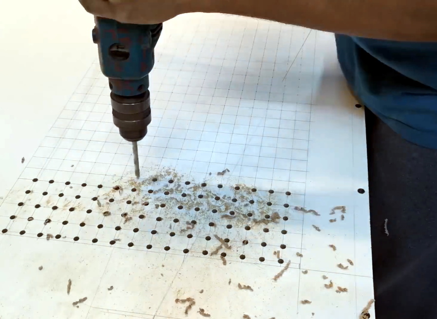
The build starts with sheets of MDF, which get cut, glued, and screwed together to make the basic tabletop shape. To this, [MakerMan] attaches a welded steel frame which will give it the strength MDF itself lacks. With careful measurement, lines are plotted across the top of the MDF sheet and all the holes are drilled with a simple hand drill; no fancy CNC here.
With the table doing its best colander impression, [MakerMan] adds an air box to the bottom which is similarly made of thin MDF sheets. All of the joints are sealed up with caulk, because at this point you want things to be as air tight as possible. A large blower is attached to the bottom, which gets piped to a dust collection system that’s made of a garbage can and…you guessed it, more MDF.
Watching [MakerMan] turn what’s often literal trash into a functional build never gets old. We’ve seen him create everything from a gorgeous origami chandelier to a very impressive diode laser cutter using little more than scrap parts and hand tools, and we can’t wait to see what he comes up with next.