When you’re like [Wes] from Watch Wes Work fame, you don’t have a CNC machine hoarding issue, you just have a healthy interest in going down CNC machine repair rabbit holes. Such too was the case with a recently acquired 2001 Milltronics ML15 lathe, that at first glance appeared to be in pristine condition. Yet despite – or because of – living a cushy life at a college’s workshop, it had a number of serious issues, with a busted Z-axis drive board being the first to be tackled.

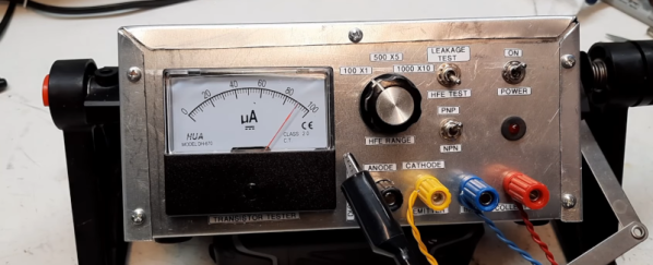
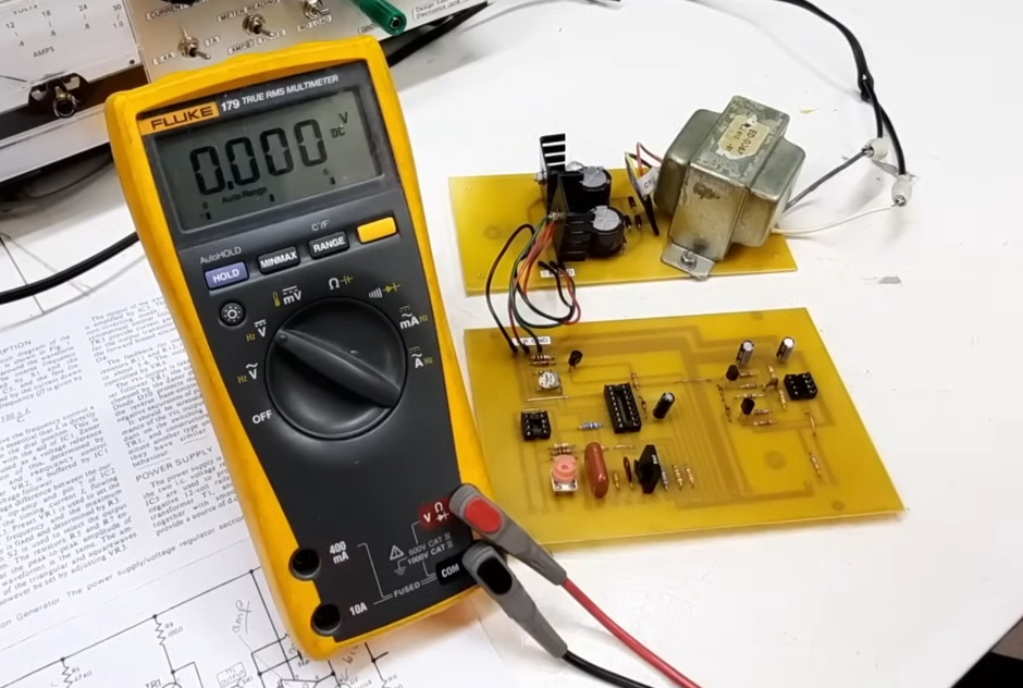
The identical servo control board next to it worked fine, so it had to be an issue on the board itself. A quick test showed that the H-bridge IGBTs had suffered the typical fate that IGBTs suffer, violently taking out another IC along with them. Enjoyably, this board by one Glentek Inc. did the rebranding thing of components like said IGBTs, which made tracking down suitable replacements an utter pain that was eased only by the desperate communications on forums which provided some clues. Of course, desoldering and testing one of the good IGBTs on the second board showed the exact type of IGBT to get.
After replacing said IGBTs, as well as an optocoupler and other bits and pieces, the servo board was good as new. Next, the CNC lathe also had a busted optical encoder, an unusable tool post and a number of other smaller and larger issues that required addressing. Along the way the term ‘pin-to-pin compatible’ for a replacement driver IC was also found to mean that you still have to read the full datasheet.
Of the whole ordeal, the Glentek servo board definitely caused the most trouble, with the manufacturer providing incomplete schematics, rebranding parts to make generic replacements very hard to find and overall just going for a design that’s interesting but hard to diagnose and fix. To help out anyone else who got cursed with a Glentek servo board like this, [Wes] has made the board files and related info available in a GitHub repository.
Continue reading “Fixing A Milltronics ML15 CNC Lathe Despite The Manufacturer’s Best Efforts”