If you’re planning to make a metalworking lathe out of a CNC milling machine, you probably don’t expect getting a position sensor to work to be your biggest challenge. Nevertheless, this was [Anthony Zhang]’s experience. Admittedly, the milling machine’s manufacturer sells a conversion kit, which greatly simplifies the more obviously difficult steps, but getting it to cut threads automatically took a few hacks.
The conversion started with a secondhand Taig MicroMill 2019DSL CNC mill, which was well-priced enough to be purchased specifically for conversion into a lathe. Taig’s conversion kit includes the spindle, tool posts, mounting hardware, and other necessary parts, and the modifications were simple enough to take only a few hours of disassembly and reassembly. The final lathe reuses the motors and control electronics from the CNC, and the milling motor drives the spindle through a set of pulleys. The Y-axis assembly isn’t used, but the X- and Z-axes hold the tool post in front of the spindle.
The biggest difficulty was in getting the spindle indexing sensor working, which was essential for cutting accurate threads. [Anthony] started with Taig’s sensor, but there was no guarantee that it would work with the mill’s motor controller, since it was designed for a lathe controller. Rather than plug it in and hope it worked, he ended up disassembling both the sensor and the controller to reverse-engineer the wiring.
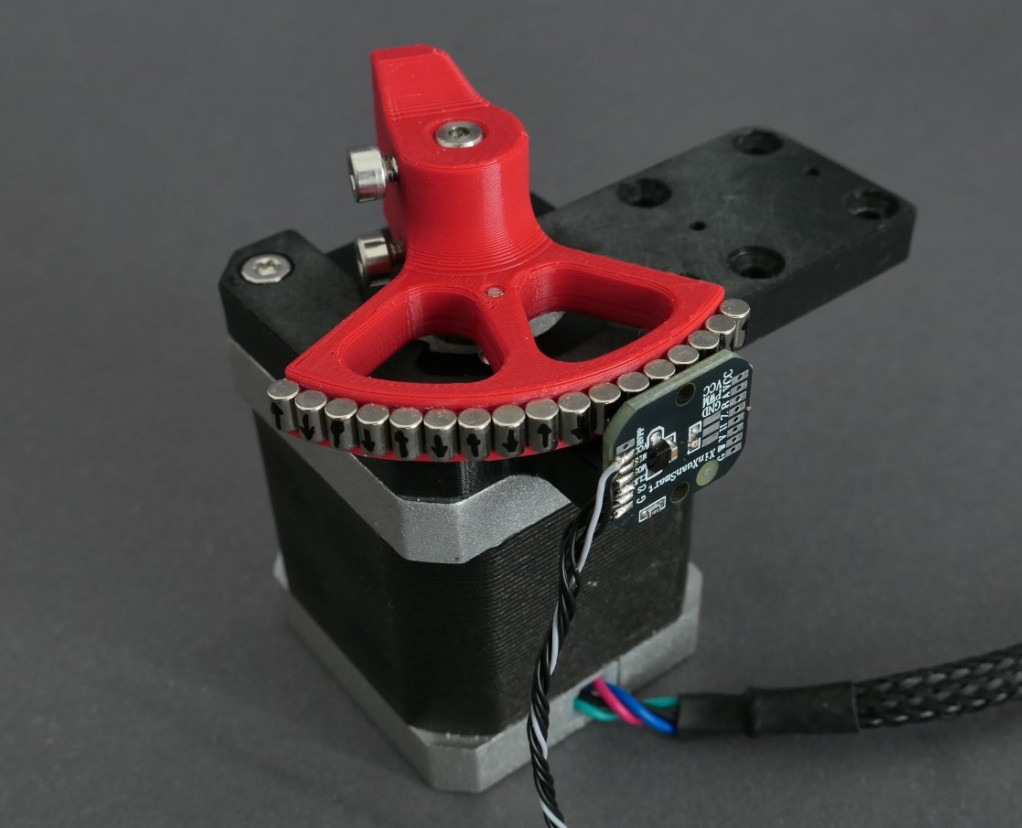
He found that it was an inductive sensor which detected a steel insert in the spindle’s pulley, and that a slight modification to the controller would let the two work together. In the end, however, he decided against using it, since it would have taken up the controller’s entire I/O port. Instead, [Anthony] wired his own I/O connector, which interfaces with a commercial inductive sensor and the end-limit switches. A side benefit was that the new indexing sensor’s mounting didn’t block moving the pulley’s drive belt, as the original had.
The end result was a small, versatile CNC lathe with enough accuracy to cut useful threads with some care. If you aren’t lucky enough to get a Taig to convert, there are quite a few people who’ve built their own CNC lathes, ranging from relatively simple to the extremely advanced.