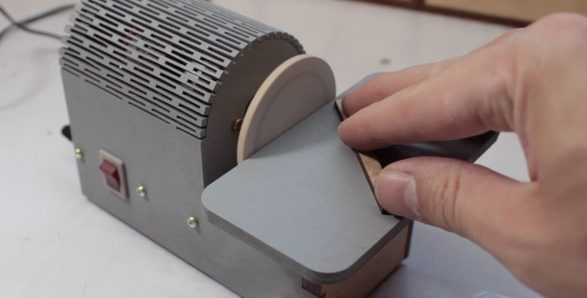
Casually browsing YouTube for “shop improvements” yields a veritable river of project ideas, objects for cat amusement, and 12 INCREDIBLE SHOP HACKS YOU WON’T BELIEVE, though some of these are of predictably dubious value. So you might imagine that when we found [Henrique]’s adorable disc sander we dismissed it out of hand, how useful could such a tiny tool be? But then we remembered the jumbo tub o’ motors on the shelf and reconsidered, maybe a palm sized sander has a place in the tiny shop.
 Electrically the build is a simple as can be. It’s just a brushed DC motor plugged into a wall wart with a barrel jack and a toggle switch. But what else does it need? This isn’t a precision machine tool, so applying the “make it out of whatever scrap” mindset seems like a much better fit than figuring out PWM control with a MOSFET and a microcontroller.
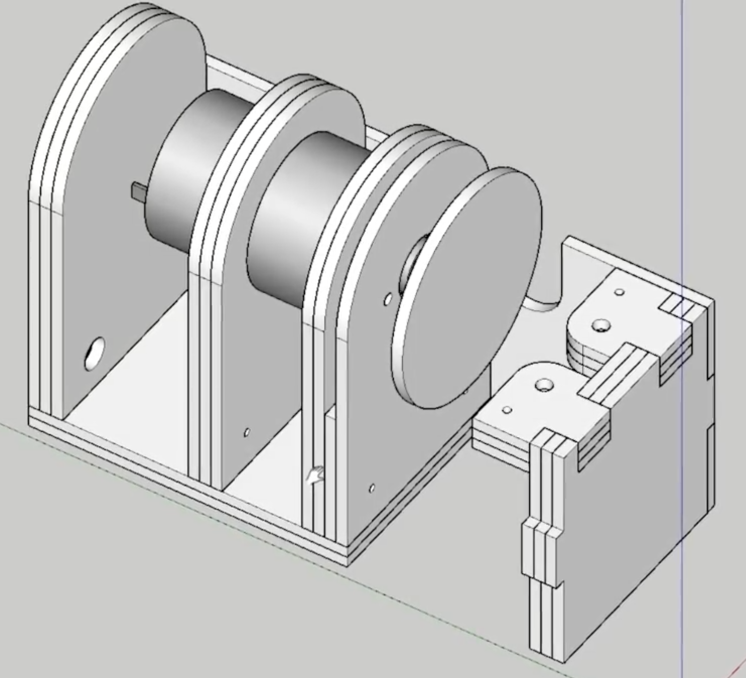
There are a couple of neat tricks in the build here. The most obvious is the classic laser-cut living hinge that we love so much. [Henrique] mentions that he buys MDF in 3 mm sheets for easy storage, so each section of the frame is built from layers that he laminates with glue himself. This trades precision and adds steps, but also give him a little flexibility. It’s certainly easier to add layers of thin stock together than it would be to carve out thicker pieces. Using the laser to precisely cut holes which are then match drilled through into the rest of the frame is a nice build acceleration too. The only improvement we can imagine would be using a shaft with a small finger chuck (like a Dremel) so it could use standard rotary tool bits to avoid making sanding disks by hand.
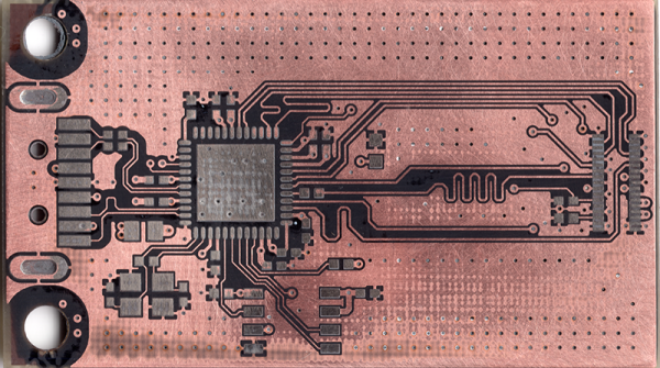
What could a tool like this be used for? There are lots of parts with small enough features to be cleaned up by such a small tool. Perhaps those nasty burrs after cutting off a bolt? Or trimming down mousebites on the edges of PCBs? (Though make sure to use proper respiration for cutting fiberglass!)
If you want to make one of these tools for your own desk, the files are here on Thingiverse. And check out the video overview after the break.
Continue reading “Adorable Desktop Disc Sander Warms Our Hearts And Our Parts”