Usually when there is a clear demand for something, some entrepreneur will fill that demand. Unfortunately, no one seems to think there’s a need for a solderless breadboard product that can handle boards that have a dual row header. These devices have 0.1″ spacing in both directions, so while they will fit in a standard breadboard, the contacts will short out the adjacent pins on the device, which makes it worthless.
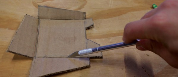
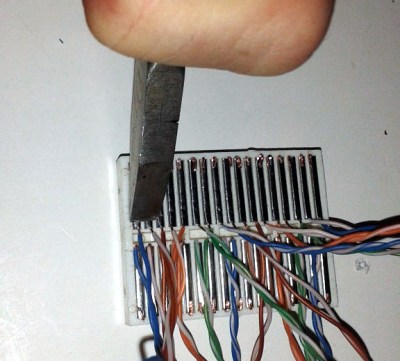
[Baz] needed to connect an RF24L01 module to a breadboard. Instead of connecting leads to the device or devising a breakout board, [Baz] actually hacked his breadboard. To make an area to plug in a dual row device, he took the breadboard apart, pulled the spring contacts, cut them, and then put them back in.
Of course, you have to make sure the cut is wide enough that the two parts of the spring won’t touch. It looks like [Baz] used a small screwdriver to help the springs keep their shape and cut them with simple diagonal cutters.
Continue reading “Literal Breadboard Hack Forces It To Accept Dual Pin Headers”
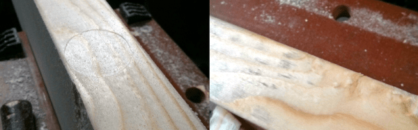
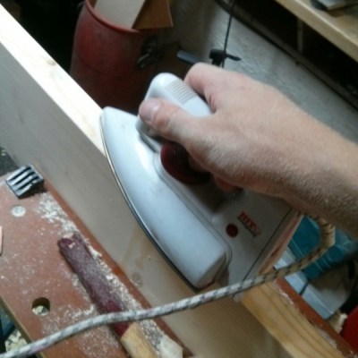 The Technique itself is dead simple and takes only a few minutes to perform. Simply apply a small amount of water, let it seep into the wood, and then bring a hot iron down onto the soaked wood to evaporate off the soaked water–instantly inflating the wood back into its original form!
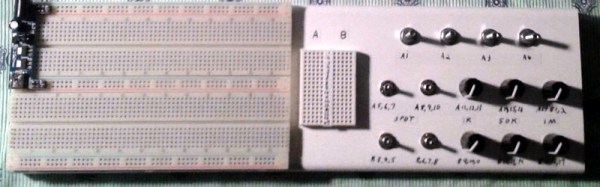
 Of course, it is easy enough to just connect breadboard wires to component, but [Chuck] went further than that. Using boxes of different types (including a cigar box), he mounted the components properly and also wired them to a breadboard for easy connection.
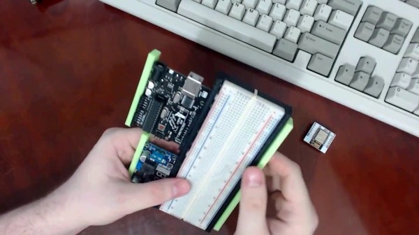
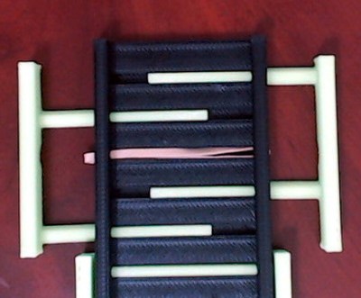 While [Pat]’s inspiration came from the aforementioned Stickvise, the new 3d-printed vice is just what you’ll need before you’re ready to do the soldering. The vice is spring-loaded using rubber bands. The base is sized to fit a standard breadboard in the center with clamping arms on either side to hold dev boards such as an Arduino. This innovative yet simple de”vice” grips boards well enough that you won’t be chasing them around your desk, knocking wires out of place, anymore.