An RF remote control with a LoRa receiver next to it

Reverse Engineering A 900 MHz RC Transmitter And Receiver

For those building their own remote controlled devices like RC boats and quadcopter drones, having a good transmitter-receiver setup is a significant factor in the eventual usability of their build. Many transmitters are available in the 2.4 GHz band, but some operate at different frequencies, like the 868/915 MHz band. The TBS Crossfire is one such transmitter, and it’s become a popular model thanks to its long-range performance.

The channel hopping sequence of a TBS Crossfire transmitter
The channel hopping sequence

When [g3gg0] bought a Crossfire set for his drone, he discovered that the receiver module consisted of not much more than a PIC32 microcontroller and an SX1272 LoRa modem. This led him to ponder if the RF protocol would be easy to decode. As it turns out, it was not trivial, but not impossible either. First, he built his own SPI sniffer using a CYC1000 FPGA board to reveal the exact register settings that the PIC32 sent to the SX1272. The Crossfire uses channel hopping, and by simply looking at the register settings it was easy to figure out the hopping sequence.

Once that was out of the way, the next step was to figure out what data was flowing through those channels. The data packets appeared to be built up in a straightforward way, but they included an unknown CRC checksum. Luckily, brute-forcing it was not hard; the checksum is most likely used to keep receivers from picking up signals that come from a different transmitter than their own.

[g3gg0]’s blog post goes into intricate detail on both the Crossfire’s protocol as well as the reverse engineering process needed to obtain this information. The eventual conclusion is that while the protocol is efficient and robust, it provides no security against eavesdropping or deliberate interference. Of course, that’s perfectly fine for most RC applications, as long as the user is aware of this fact.

If you’re into decoding RF protocols, you might also want to try using a logic analyzer. But if you merely want to replicate an existing transmitter’s signals, it might be easier to simply spoof a few button presses.

Continue reading “Reverse Engineering A 900 MHz RC Transmitter And Receiver”

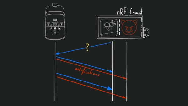
Palm portable keyboard gone Bluettoh

Palm Portable Keyboard Goes Wireless

Long ago when digital portables where in their infancy, people were already loath to type on tiny keyboards, stylus or not. So Palm made a sweet little portable keyboard that would fold up and fit in your cargo pocket. And what do we have now for luxury typing on the go? Rubber roll-up jelly keebs? That’s a hard no from this scribe.

But why mess with the success of the the Palm Portable Keyboard? It just needs to be updated for our times, and that’s exactly what [Xinming Chen] did with their PPK Bluetooth adapter.

Inspired by the work of [cy384] to make a USB adapter as well as [Christian]’s efforts with the ESP32, [Xinming Chen] points out that this version is more power efficient, easier to program, and has a built-in Li-Po charging circuit. It also uses the hardware serial port instead of the software serial, which saves brainpower.

There’s really not much to this build, which relies on the Adafruit Feather nRF52840 and will readily work with Palm III and Palm V keyboards. Since the PPK is RS-232 and needs to be TTL, this circuit also needs a voltage level inverter which can be made with a small handful of components. We love that there’s a tiny hidden switch that engages the battery when the adapter clicks on to the connector.

The schematic, code, and STL files are all there in the repository, so go pick up one of these foldy keebs for cheap on the electronic bay while they’re still around. Watch the demo video unfold after the break.

Want an all-in-one solution for typing on the go? Check out the history of tiny computers.

Continue reading “Palm Portable Keyboard Goes Wireless”

Remote control PCB next to its shell, with a breadboarded analog switch connected to the remote's onboard microcontroller, soldered to the pins responsible for button reading

Reusing Proprietary Wireless Sockets Without Wireless Hacking

Bending various proprietary devices to our will is a hacker’s rite of passage. When it comes to proprietary wall sockets, we’d often reverse-engineer and emulate their protocol – but you can absolutely take a shortcut and, like [oaox], spoof the button presses on the original remote! Buttons on such remotes tend to be multiplexed and read as a key matrix (provided there’s more than four of them), so you can’t just pull one of the pads to ground and expect to not confuse the microcontroller inside the remote. While reading a key matrix, the controller will typically drive rows one-by-one and read column states, and a row or column driven externally will result in the code perceiving an entire group of keys as “pressed” – however, a digitally-driven “switch” doesn’t have this issue!

One way to achieve this would be to use a transistor, but [oaox] played it safe and went for a 4066 analog multiplexer, which has a higher chance of working with any remote no matter the button configuration, for instance, even when the buttons are wired as part of a resistor network. As a bonus, the remote will still work, and you will still be able to use its buttons for the original purpose – as long as you keep your wiring job neat! When compared to reverse-engineering the protocol and using a wireless transmitter, this also has the benefit of being able to consistently work with even non-realtime devices like Raspberry Pi, and other devices that run an OS and aren’t able to guarantee consistent operation when driving a cheap GPIO-operated RF transmitter.

In the past, we’ve seen people trying to tackle this exact issue, resorting to RF protocol hacking in the end. We’ve talked about analog multiplexers and switches in the past, if you’d like figure out more ways to apply them to solve your hacking problems! Taking projects like these as your starting point, it’s not too far until you’re able to replace the drift-y joysticks on your Nintendo Switch with touchpads!

Casually Chirping Into The World Of LoRaWAN

While wireless communications are unquestionably useful in projects, common wireless protocols such as WiFi and Bluetooth peter out after only a number of meters, which is annoying when your project is installed in the middle of nowhere. Moving to an LTE-based or similar mobile solution can help with the range, but this does not help when there’s poor cell coverage, and it tends to use more power. Fortunately, for low-bitrate, low-power wide-area networks (LPWAN) like e.g. sensor networks, there’s a common solution in the form of LoRaWAN, as in long-range wide area network (WAN).

The proprietary LoRa RF modulation technique that underlies LoRaWAN is based on Chirp Spread Spectrum (CSS). This modulation technique is highly resistant to channel noise and fading as well as Doppler shift, enabling it to transmit using relatively low power for long distances. LoRaWAN builds on top of the physical layer provided by LoRa to then create the protocol that devices can then use to communicate with other LoRa devices.

Courtesy of global LoRaWAN gateway and software providers such as The Things Industries and ThingSpeak, it’s possible even as a hobbyist to set up a LoRaWAN-powered sensor network with minimal cost. Let’s take take a look at exactly what is involved in setting up LoRaWAN devices, and what possible alternatives to LoRaWAN might be considered. Continue reading “Casually Chirping Into The World Of LoRaWAN”

Adding WiFi Remote Control To Home Electronics? Be Prepared To Troubleshoot

[Alex] recently gave a Marantz audio amplifier the ability to be remotely-controlled via WiFi by interfacing an ESP32 board to a handy port, but the process highlights how interfacing to existing hardware often runs into little, unforeseeable problems that can sink the project unless solved.

At its core, the project uses an ESP32 and the ESPAsyncWebServer project to create a handy web interface that is accessible over WiFi. Then, to actually control the amplifier, [Alex] decoded the IR-based remote signals by watching the unit’s REMOTE ports, which are intended as a pass-through and repeater for IR signals to other Marantz units. This functionality can be exploited; by sending the right signals to the REMOTE IN port, the unit can be controlled by the ESP32. With the ESP32 itself accessible by just about any WiFi device, [Alex] gains the freedom to control his amplifier with much greater flexibility than just the IR remote would offer.

Sounds fairly straightforward, but as usual when interfacing to an existing piece of electronics, there were a few glitches. The first was that high and inconsistent latency (from 10 ms to 100 ms) made controlling the amplifier a sometimes frustrating experience, but that was solved by disabling power saving on the WiFi interface. Another issue was that sending signals by connecting a GPIO pin to the REMOTE IN port of the amplifier worked, but had the side effect of causing the amplifier to no longer listen to the IR remote. Apparently, current flowing from the REMOTE port to the ESP32’s GPIO pin was to blame, because adding a diode in between fixed the problem.

The GitHub repository holds the design files and code. This kind of project can be pretty complex, because the existing hardware doesn’t always play nice, and useful boards like a modern ESP32 aren’t always available. Adding a wireless interface to vintage audio equipment has in the past involved etching circuit boards and considerably more parts.

New Pi Zero Gains Unapproved Antennas Yet Again

We’ve only started to tap into the potential of the brand new Pi Zero 2. Having finally received his board, [Brian Dorey] shows us how to boost your Pi’s WiFi, the hacker way. Inline with the onboard WiFi antenna can be found a u.FL footprint, and you just know that someone had to add an external antenna. This is where [Brian] comes in, with a photo-rich writeup and video tutorial, embedded below, that will have you modify your own Zero in no time. His measurements show seeing fourteen networks available in a spot where he’d only see four before, and the RSSI levels reported have improved by 5 dB -10 dB, big when it comes to getting a further or more stable connection.

With old laptops being a decent source of WiFi antennas, you only need to procure a u.FL connector and practice soldering a bit before you take this on! The hardest part of such a project tends to be not accidentally putting any solder on the u.FL connector’s metal can – and [Brian] mostly succeeds in that! He shows how to disconnect the external antenna to avoid signal reflections and the like, and, of course, you will be expected to never power your Pi Zero on without an attached antenna afterwards, lest you have your transmitter become fatally confused by the mismatch of hardware-defined impedance expectations. A Pi Zero isn’t the only place where you’ll encounter footprints for connectors you can add, and arguably, that’s your duty as a hacker – modifying the things you work with in a way that adds functionality. Don’t forget to share how you did it!

This trick should be pretty helpful if you’re ever to put your new Pi Zero in a full-metal enclosure. Curious about the Raspberry Pi antenna’s inner workings? We’ve covered them before! If you’d like to see some previous Raspberry Pi mods, here’s one for the Pi 3, and here’s one for the original Zero W – from [Brian], too!
Continue reading “New Pi Zero Gains Unapproved Antennas Yet Again”

wifi scanner

Visualizing WiFi With A Converted 3D Printer

We all know we live in a soup of electromagnetic radiation, everything from AM radio broadcasts to cosmic rays. Some of it is useful, some is a nuisance, but all of it is invisible. We know it’s there, but we have no idea what the fields look like. Unless you put something like this 3D WiFi field strength visualizer to work, of course.

Granted, based as it is on the gantry of an old 3D printer, [Neumi]’s WiFi scanner has a somewhat limited work envelope. A NodeMCU ESP32 module rides where the printer’s extruder normally resides, and scans through a series of points one centimeter apart. A received signal strength indicator (RSSI) reading is taken from the NodeMCU’s WiFi at each point, and the position and RSSI data for each point are saved to a CSV file. A couple of Python programs then digest the raw data to produce both 2D and 3D scans. The 3D scans are the most revealing — you can actually see a 12.5-cm spacing of signal strength, which corresponds to the wavelength of 2.4-GHz WiFi. The video below shows the data capture process and some of the visualizations.

While it’s still pretty cool at this scale, we’d love to see this scaled up. [Neumi] has already done a large-scale 3D visualization project, using ultrasound rather than radio waves, so he’s had some experience in this area. But perhaps a cable bot or something similar would work for a room-sized experiment. A nice touch would be using an SDR dongle to collect signal strength data, too — it would allow you to look at different parts of the spectrum.

Continue reading “Visualizing WiFi With A Converted 3D Printer”