Do You Need A Cycloidal Drive?

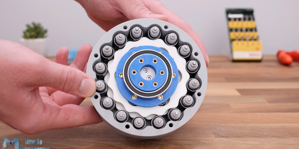
A cycloidal gear drive is one of the most mesmerizing reduction gears to watch when it is running, but it’s not all just eye-candy. Cycloidals give decent gearing, are relatively compact and back-drivable, and have low backlash and high efficiency. You probably want one in the shoulder of your robot arm, for instance.

But designing and building one isn’t exactly straightforward. Thanks, then, to [How To Mechatronics] for the lovely explanation of how it works in detail, and a nice walkthrough of designing and building a cycloidal gear reducer out of 3D printed parts and a ton of bearings. If you just want to watch it go, check out the video embedded below.

The video is partly an ad for SolidWorks, and spends a lot of time on the mechanics of designing the parts for 3D printing using that software. Still, if you’re using any other graphical CAD tool, you should be able to translate what you learned.

It’s amazing that 3D printing has made sophisticated gearbox designs like this possible to fabricate at home. This stuff used to be confined to the high-end machine shops of fancy robotics firms, and now you can make one yourself this weekend. Not exotic or unreliable enough for you? Well, then, buy yourself some flexible filament and step on up to the strain wave, aka “harmonic drive”, gearbox.

Thanks to serial tipster [Keith] for the tip!
Continue reading “Do You Need A Cycloidal Drive?” →

Keycap Customizer Brings All Your Caps To The Board

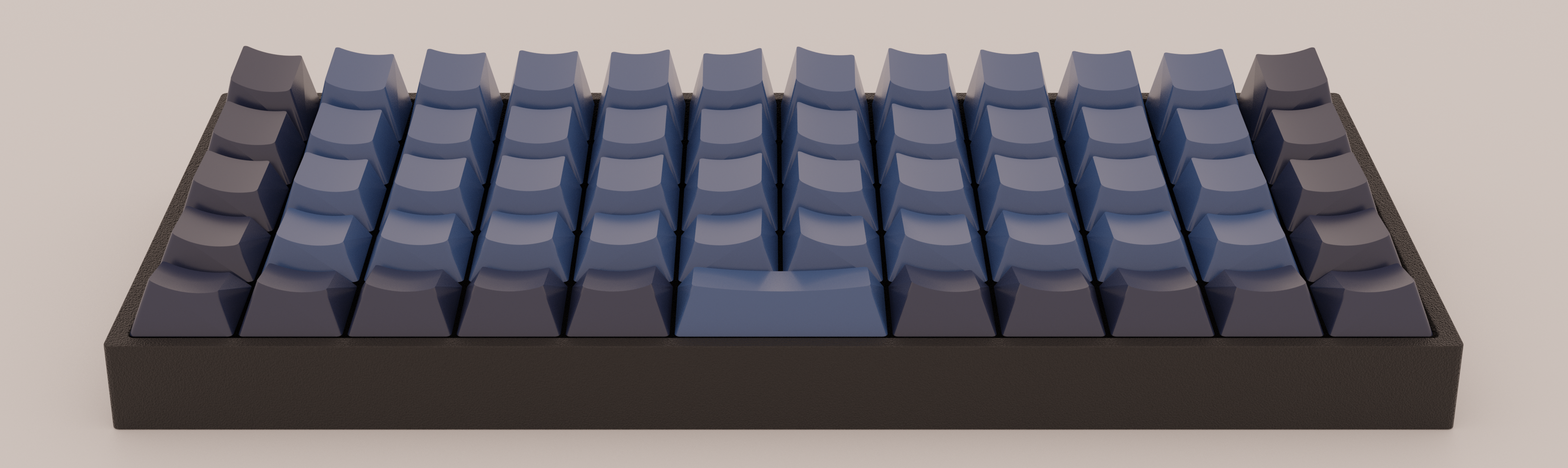
With bright colors and often intricate designs, after the physical shape of a keyboard the most conspicuous elements are surely the keycaps. Historically dictated by the stem of the key switch it attaches to, keycaps come in a variety of sizes, colors, profiles, and designs. As they necessarily include small features with tight tolerances to fit the stem of their key switch, injection molding is the classic manufacturing technique for a keycap. But as hobbyist 3D printing matures and resin printers become more accessible, home keycap manufacturing is increasingly good option. Instead of designing each cap by hand, consider trying [rsheldiii]’s KeyV2 OpenSCAD script to create custom caps with ease.

To cover the basics, KeyV2 can generate full keycap sets with Cherry or Alps stems, in the SA, DSA, DCS profiles (and more!) for any typically sized keyboard. Generating a particular cap of arbitrary profile, position, and size is just a short chain of function calls away. But standard keycap sets aren’t the highlight of this toolset.

If you’re not an OpenSCAD aficionado yet, visit [Brian Benchoffs] great getting-started guide or our other coverage to get a feel for what the tool can do. Part of OpenSCAD’s attraction is that it is the the paragon of parametric modeling. It’s declarative part files ensure that no parameter goes undefined, which is a perfect fit for KeyV2.

The root file upon which all caps are based on has about 150 keycap parameters which can be tweaked, and that’s before more elaborate customization. Making simple “artisan” caps is a snap, as the magic of OpenSCAD means the user can perform any Boolean operations they need on top of the fully parameterized keycap. Combining an arbitrary model with a keycap is one union() away. See the README for examples.

For the prospective user of KeyV2 worried about complexity; don’t be, the documentation is a treat. Basic use to generate standard keycaps is simple, and there are plenty of commented source files and examples to make more complex usage easy. Thinking about a new keyboard? Check out our recent spike in clacky coverage.

Try NopSCADlib For Your Next OpenSCAD Project

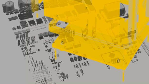
Most readers of this site are familiar by now with the OpenSCAD 3D modeling software, where you can write code to create 3D models. You may have even used OpenSCAD to output some STL files for your 3D printer. But for years now, [nophead] has been pushing OpenSCAD further than most, creating some complex utility and parts libraries to help with modeling, and a suite of Python scripts that generate printable STLs, laser-ready DXFs, bills of material, and human-readable assembly instructions complete with PNG imagery of exploded-view sub-assemblies.

Recently [nophead] tidied all of this OpenSCAD infrastructure up and released it on GitHub as NopSCADlib. You can find out more by browsing through the example projects and README file in the repository, and by reading the announcement blog post on the HydraRaptor blog. Some functionality highlights include:

  • a large parts library full of motors, buttons, smooth rod, et cetera
  • many utility functions to help with chamfers, fillets, precision holes, sub-assemblies, and BOM generation
  • Python scripts to automate the output of STLs, DXFs, and BOMs
  • automatic creation of documentation from Markdown embedded in your OpenSCAD files
  • automatic rendering of exploded subassemblies

All that’s missing is a nice Makefile to tie it all together! Try it out for your next project if you – like us – get giddy at the thought of putting your 3D projects into version control before “compiling” them into the real world.

We’ve discussed some complex OpenSCAD before: Mastering OpenSCAD Workflow, and An OpenSCAD Mini-ITX Computer Case.

Ask Hackaday: Help Me Pick A CAD Package

Of all the skills that I have picked up over the years as an engineer, there is one that has stayed with me and been a constant over the last three decades. It has helped me work on electronic projects, on furniture, on car parts, robots, and even garments, and it is likely that I will continue using it periodically for the rest of my career. You see, I am a trained PAD expert.

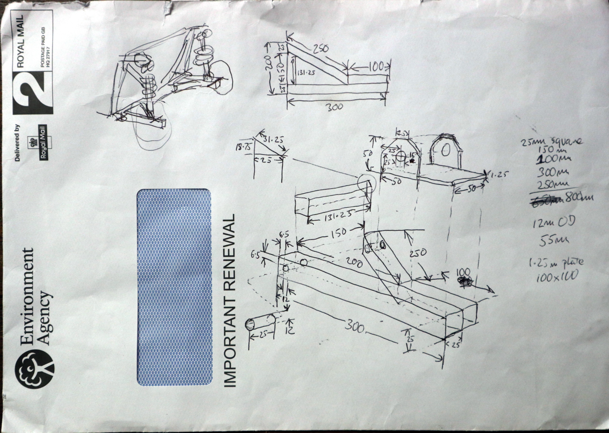
Don't build this, it's fundamentally flawed! Sometimes the front of an envelope is as effective as its back.
Don’t build this, it’s fundamentally flawed! Sometimes the front of an envelope is as effective as its back.

PAD, you ask? OK, it’s an acronym of my own coinage, it stands for Pencil Aided Design, and it refers to the first-year undergraduate course I sat many years ago in which I learned technical drawing to the old British standard BS308. If I’m making something then by far the quickest way for me to visualise its design is to draw it, first a freehand sketch to get a feel of how everything will sit, then a series of isometric component drawings on graph paper with careful attention to dimensions and angles. Well, maybe I lied a little there, the graph paper only comes in when I’m doing something very fancy; the back of an envelope is fine as long as the dimensions on the diagram are correct.

Continue reading “Ask Hackaday: Help Me Pick A CAD Package” →

Ditch OpenSCAD For C++

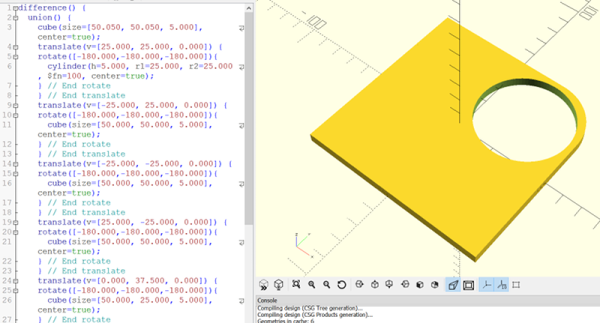
There’s an old saying that a picture is worth a thousand words. If you’ve ever tried to build furniture or a toy with one of those instructions sheets that contains nothing but pictures, you might disagree. 3D design is much the same for a lot of people. You think you want to draw things graphically, but once you start doing complex things and making changes, parametric modeling is the way to go. Some CAD tools let you do both, but many 3D printer users wind up using OpenSCAD which is fully parametric.

If you’ve used OpenSCAD you know that it is like a simple programming language, but with some significant differences from what you normally use. It is a good bet that most Hackaday readers can program in at least one language. So why learn something new? A real programming language is likely to have features you won’t find readily in OpenSCAD that, in theory, ought to help with reuse and managing complex designs.

I considered OpenJSCAD. It is more or less OpenSCAD for JavaScript. However, JavaScript is a bit of a scripting language itself. Sure, it has objects and some other features, but I’m more comfortable with C++. I thought about using the OpenCSG library that OpenSCAD uses, but that exposes a lot of detail.

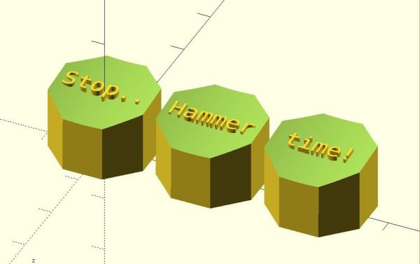
Instead, I turned to a project that uses C++ code to generate OpenSCAD output, OOML (the Object Oriented Mechanics Language)). OpenSCAD does the rendering, exporting, and other functions. Unfortunately, the project seems to have stalled a few years back and the primary web-based documentation for it seems to be absent. However, it is very usable and if you know how to find it, there is plenty of documentation available.

Why not OpenSCAD?

Continue reading “Ditch OpenSCAD For C++” →

Wireless Robotic Gripper With Haptic Feedback

We’re not sure what kind of, “High School,” [Sam Baumgarten] and [Graham Hughes] go to that gave them the tools to execute their robotic gripper so well. We do know that it was not like ours. Apparently some high schools have SLS 3D printers and Solidworks. Rather than a grumpy shop teacher with three fingers who, despite that, kept taking the safety off the table saws and taught drafting on boards with so many phalluses and names carved into the linoleum, half the challenge was not transferring them to the line work.

Our bitterness aside, [Sam] and [Graham] built a pretty dang impressive robotic gripper. In fact, after stalking [Sam]’s linkedin to figure out if he was the teacher or the student, (student) we decided they’re bright enough they could probably have built it out of scraps in a cave. Just like [HomoFaciens], and Ironman.

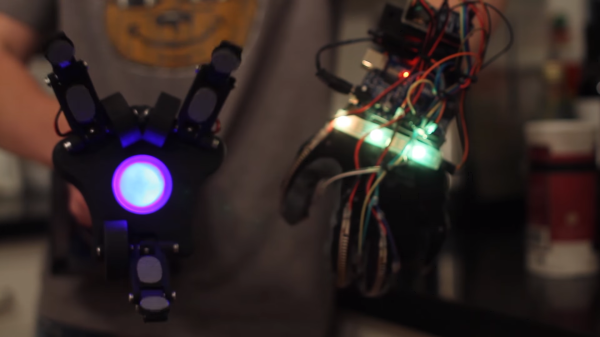
The gripper itself is three large hobby servos joined to the fingers with a linkage, all 3D printed. The mechanical fingers have force sensors at the contact points and the control glove has tiny vibrating motors at the fingertips. When the force of the grip goes up the motors vibrate more strongly, providing useful feedback. In the video below you can see them performing quite a bunch of fairly fine motor skills with the gripper.

The gripper is mounted on a pole with some abrasive tape, the kind found on skateboard decks. At the back of the pole, the electronics and batteries live inside a project box. This provides a counterbalance to the weight of the hand.

The control glove has flexible resistors on the backs of the fingers. The signal from these are processed by an Arduino which transmits to its  partner arduino in the gipper via an Xbee module.

[Sam] and [Graham] did a great job. They worked through all the design stages seen in professional work today. Starting with a napkin sketch they moved onto digital prototyping and finally ended up with an assembly that worked as planned. A video after the break explaining how it works along with a demo video.

Continue reading “Wireless Robotic Gripper With Haptic Feedback” →

ImplicitCAD: Programmatic CAD Built With 3D Printing In Mind

Cornerstone of many useful things: This Prusa i3 part was modeled in OpenSCAD.

Programmatic CAD, in particular the OpenSCAD language and IDE, has accompanied the maker movement for a while now. After its introduction in 2009, it quickly found its way into the 3D printing toolbox of many makers and eventually became what could be called an Industry Standard among open hardware labs, makerspaces and tinkerers. The Prusa i3, one of the most popular DIY 3D printers, was designed in OpenSCAD, and even Makerbot, the company that sold 100.000 3D printers, uses the language for its “Customizer” – an online tool that allows users to customize 3D printable models with minimal effort.

OpenSCAD is indeed a wonderful tool, and we have been using it a lot. We have become used to its quirks and accepted working with polygon mesh approximations of the models we are trying to design. We have made our peace with excessive rendering times, scripting workarounds and the pain of creating fillets, and we have learned to keep our aesthetic expectations low. We are happy with the fact that there is a way to programmatically create and share virtually any object, but sometimes we wish there was a better way in the open source world. Hint: there is.

Continue reading “ImplicitCAD: Programmatic CAD Built With 3D Printing In Mind” →