New Browser-based CAD System Is Best Friends With Triangle Meshes

Who’s interested in a brand new, from-scratch boundary representation (BREP) kernel? How about one that has no topological naming problem, a web-native parametric CAD front end to play with, and has CAD-type operations making friends with triangle meshes? If you’re intrigued, check out [mmiscool]’s BREP project.

Functioning (let alone feature-filled, or efficient) CAD systems are not a software project we see a whole lot of. Ones that represent models as genuine BREP structures but cleverly use mesh-based operations where it makes sense? Even less so.

In theory, CAD programs are simple: allow a user to define features, keep track of what they are and how they relate to one another, and perform operations on them as requested. In practice, it’s significant work. Chains of operations and dependencies easily become complex, volatile things and there is really no room for error.

Read [Arya Voronova]’s best practices for using FreeCAD to get a few hints as to what goes on behind the scenes in a modern CAD program, and the kinds of challenges the back end has to deal with, like the topological naming problem (TNP). A problem [mmiscool]’s implementation completely avoids, by the way.

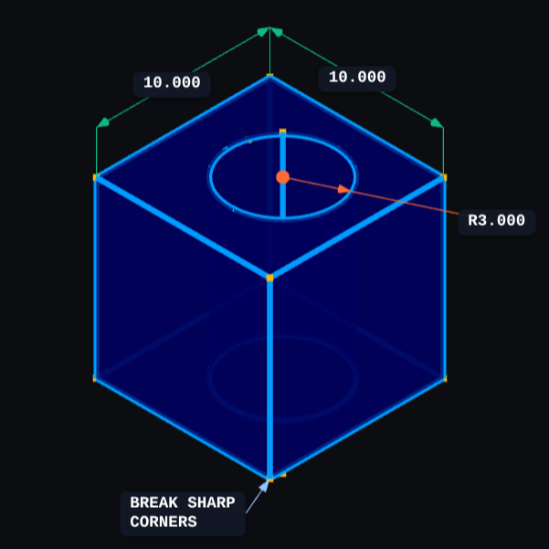
There is a live demo at BREP.io which acts as a playground for the state of the project. You can get started by clicking the + button towards the top on the left panel to add features and operations to the history (like add a cube, then add chamfers or fillets, or extrude a face, and so on).

[mmiscool] points out that all computation is done client-side; even complex operations like fillets, lofts, and multi-body booleans execute directly in the browser with no need to be offloaded to a back end. BREP’s development is being documented on Hackaday.io and there is a video embedded below that gives an overview. Why don’t you give it a spin?

Continue reading “New Browser-based CAD System Is Best Friends With Triangle Meshes”

MicroCAD Programs CAD

We love and hate OpenSCAD. As programmers, we like describing objects we want to 3D print or otherwise model. As programmers, we hate all the strange things about OpenSCAD that make it not like a normal programming language. Maybe µCAD (or Microcad) is the answer. This new entry in the field lets you build things programmatically and is written in Rust.

In fact, the only way to get it right now is to build it from source using cargo. Assuming you already have Rust, that’s not hard. Simply enter: cargo install microcad. If you don’t already have Rust, well, then that’s a problem. However, we did try to build it, and despite having the native library libmanifold available, Rust couldn’t find it. You might have better luck.

Continue reading “MicroCAD Programs CAD”

SolidWorks Certification… With FreeCAD?

There are various CAD challenges out there that come with bragging rights. Some, like the Certified Solid Works Professional Exam (CWSP) might actually look good on a resume. [Deltahedra] is apparently not too interested in padding his resume, nor does he have much interest in SolidWorks, and so decided to conquer the CWSP with FreeCAD in the name of open source — and to show us all how he did it. 

Because these CAD exams are meant to show your chops with the program, the resulting video makes an awesome FreeCAD tutorial. Spoiler alert: he’s able to model the part, though it takes him about 15 minutes. After modeling the part, the CWSP exam needs you to find the mass of the part, which [Deltahedra] does with the FCInfo macro — which, of course, he shows us how to install and use. The second and third questions are similar: change some variables (it is a parametric modeling software, after all) and find the new mass. In a second exercise, he needs to modify the model according to a new drawing. Modifying existing models can sometimes be more difficult than creating them, but [Deltahedra] and FreeCAD pass with flying colors once again.

If you’re at all curious about what FreeCAD can do, this video is a really impressive demonstration of FreeCAD’s part modeling workbench. We’ve had a few FreeCAD guides of our on on Hackaday, like this one on reverse engineering STLs and this one on best practices in the software, but if you’d asked us before the release of v1.0 we’d never have guessed you could use it for a SolidWorks exam in 2025. So while there are kudos due to [Deltahedra], the real accolades belong to the hardworking team behind FreeCAD that has brought it this far. Bravo!

Continue reading “SolidWorks Certification… With FreeCAD?”

Open Source CAD In The Browser

Some people love tools in their browsers. Others hate them. We certainly do like to see just how far people can push the browser and version 0.6 of CHILI3D, a browser-based CAD program, certainly pushes.

If you click the link, you might want to find the top right corner to change the language (although a few messages stubbornly refuse to use English). From there, click New Document and you’ll see an impressive slate of features in the menus and toolbars.

The export button is one of those stubborn features. If you draw something and select export, you’ll see a dialog in Chinese. Translated it has the title: Select and a checkmark for “Determined” and a red X for “Cancelled.” If you select some things in the drawing and click the green checkmark, it will export a brep file. That file format is common with CAD programs, but you’ll need to convert, probably, if you want to 3D print your design.

The project’s GitHub repository shows an impressive slate of features, but also notes that things are changing as this is alpha software. The CAD kernel is a common one brought in via WebAssembly, so there shouldn’t be many simple bugs involving geometry.

We’ve seen a number of browser-based tools that do some kind of CAD. CADmium is a recent entry into the list. Or, stick with OpenSCAD. We sometimes go low-tech for schematics.

ChatGPT Makes A 3D Model: The Secret Ingredient? Much Patience

ChatGPT is an AI large language model (LLM) which specializes in conversation. While using it, [Gil Meiri] discovered that one way to create models in FreeCAD is with Python scripting, and ChatGPT could be encouraged to create a 3D model of a plane in FreeCAD by expressing the model as a script. The result is just a basic plane shape, and it certainly took a lot of guidance on [Gil]’s part to make it happen, but it’s not bad for a tool that can’t see what it is doing.

The first step was getting ChatGPT to create code for a 10 mm cube, and plug that in FreeCAD to see the results. After that basic workflow was shown to work, [Gil] asked it to create a simple airplane shape. The resulting code had objects for wing, fuselage, and tail, but that’s about all that could be said because the result was almost — but not quite — completely unlike a plane. Not an encouraging start, but at least the basic building blocks were there. Continue reading “ChatGPT Makes A 3D Model: The Secret Ingredient? Much Patience”

Signed Distance Functions: Modeling In Math

What if instead of defining a mesh as a series of vertices and edges in a 3D space, you could describe it as a single function? The easiest function would return the signed distance to the closest point (negative meaning you were inside the object). That’s precisely what a signed distance function (SDF) is. A signed distance field (also SDF) is just a voxel grid where the SDF is sampled at each point on the grid. First, we’ll discuss SDFs in 2D and then jump to 3D.

SDFs in 2D

A signed distance function in 2D is more straightforward to reason about so we’ll cover it first. Additionally, it is helpful for font rendering in specific scenarios. [Vassilis] of [Render Diagrams] has a beautiful demo on two-dimensional SDFs that covers the basics. The naive technique for rendering is to create a grid and calculate the distance at each point in the grid. If the distance is greater than the size of the grid cell, the pixel is not colored in. Negative values mean the pixel is colored in as the center of the pixel is inside the shape. By increasing the size of the grid, you can get better approximations of the actual shape of the SDF. So, why use this over a more traditional vector approach? The advantage is that the shape is represented by a single formula calculated at many points. Most modern computers are extraordinarily good at calculating the same thing thousands of times with slightly different parameters, often using the GPU. GLyphy is an SDF-based text renderer that uses OpenGL ES2 as a shader, as discussed at Linux conf in 2014. Freetype even merged an SDF renderer written by [Anuj Verma] back in 2020. Continue reading “Signed Distance Functions: Modeling In Math”

GhostSCAD: Marrying OpenSCAD And Golang

It’s been at least a couple of months since we’ve seen a different 3D modeling language project, so here’s [Lukasz Janyst] with GhostSCAD: a take on creating OpenSCAD models, using the Go language as the front end, bringing all the delights this modern modular language has to offer (and a few of its own idiosyncrasies.) As [Lukasz] says in the blog, from a programmer’s viewpoint, openSCAD has a number of failings that make it not necessarily hard, just kinda annoying to work with, due to the way the geometry tree works. The OpenSCAD way of working ends up with the programmer requiring knowledge of the internal workings of sub-modules, in order to work at the top level (assembly) which is not an ideal situation from a code reuse perspective.

A programmer would describe this problem as “abstraction leakage” and it doesn’t make modular, reusable coding easy to do without a lot of extra work. [Lukasz] says regarding the example GhostSCAD project, that some parts were modeled in a way that knowledge was needed of some mounting points of sub-modules, but those sub-modules had no way to expose this information to the outside world. GhostSCAD enables the programmer to define parts that expose specific parameters to the world that can be queried, for example, to produce a joining part, or an exploded assembly diagram. These properties can be interpreted without the querying module having any knowledge of the internal structure of the thing it’s working with. GhostSCAD provides a Java3D-like API for defining the geometry tree, which may be familiar to some.

Continue reading “GhostSCAD: Marrying OpenSCAD And Golang”