Editing video tends to involve a lot of keyboard shortcuts, and while this might be fine for the occasional edit, those who regularly deal with video often reach for a macro pad to streamline their workflow. There are plenty of macro keyboards available specifically meant to meet the needs of those who edit a lot of video, but if you want something tailored for your personal workflow you may want to design your own keyboard like this wooden macro pad from [SS4H].
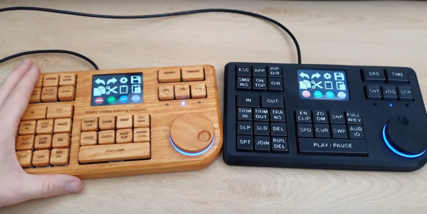
The keyboard itself is built around an STM32 microcontroller, which gives it plenty of power to drive and read the keyboard matrix. It also handles an encoder that is typically included on macro keyboards for video editing, but rather than using a potentiometer-type encoder this one uses a magnetic rotary encoder for accuracy and reliability. There’s a display built into the keyboard as well with its own on-board microcontroller that needs to be programmed separately, but with everything assembled it looks like a professional offering.
[SS4H] built a prototype using 3D printed parts, but for the final version he created one with a wooden case and laser etched keys to add a bit of uniqueness to the build. He also open-sourced all of the PCB schematics and other files needed to recreate this build so anyone can make it if they’d like. It’s not the only macro keyboard we’ve seen before, either, so if you’re looking for something even more esoteric take a look at this keyboard designed to be operated by foot.