When somebody builds a quadcopter with the express purpose of flying it as fast and aggressively as possible, it’s not exactly a surprise when they eventually run it into an immovable object hard enough to break something. In fact, it’s more like a rite of passage. Which is why many serious fliers will have a 3D printer at home to rapidly run off replacement parts.
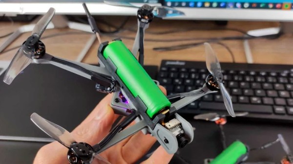
Avid first person view (FPV) flier [David Cledon] has taken this concept to its ultimate extreme by designing a 3D printable quadcopter that’s little more than an 18650 cell with some motors attached. Since the two-piece frame can be produced on a standard desktop 3D printer in a little over two hours with less than $1 USD of filament, crashes promise to be far less stressful. Spend a few hours during the week printing out frames, and you’ll have plenty to destroy for the weekend.
 While [David] says the overall performance of this diminutive quadcopter isn’t exactly stellar, we think the 10 minutes of flight time he’s reporting on a single 18650 battery is more than respectable. While there’s still considerable expense in the radio and video gear, this design looks like it could be an exceptionally affordable way to get into FPV flying.
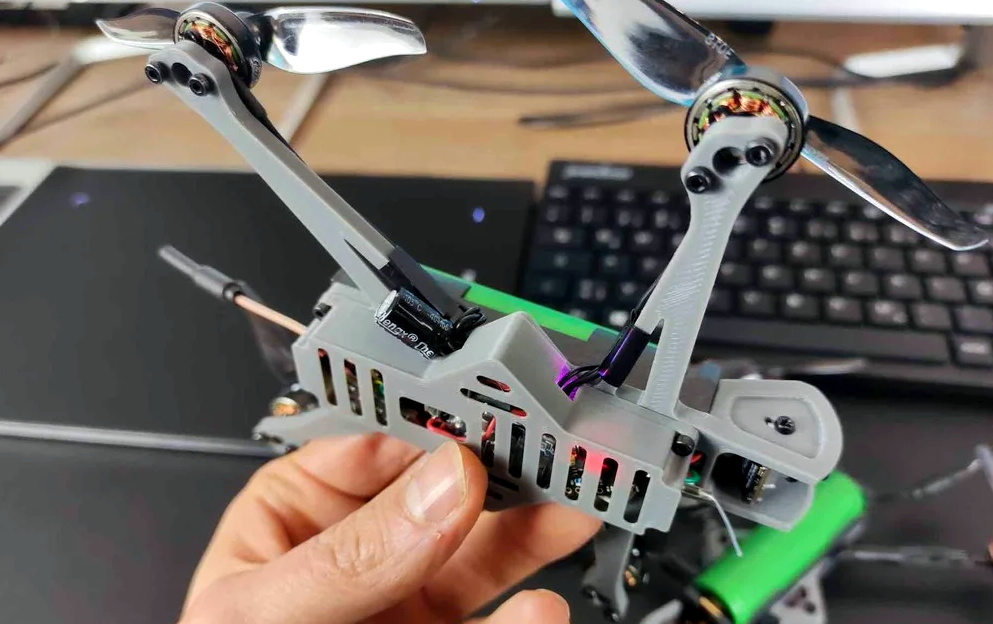
Of course, the argument could be made that such a wispy quadcopter is more likely to be obliterated on impact than something larger and commercially produced. There’s also a decent amount of close-quarters soldering involved given the cramped nature of the frame. So while the total cost of building one of these birds might be appealing to the newbie, it’s probably a project best left to those who’ve clocked a few hours in on the sticks.
We’ve seen quite a few 3D printed quadcopter frames over the years, but certainly none as elegant as what [David] has created here. It’s an experiment in minimalism that really embraces the possibilities afforded by low-cost desktop 3D printing, and we wouldn’t be surprised to see it become the standard by which future designs are measured.