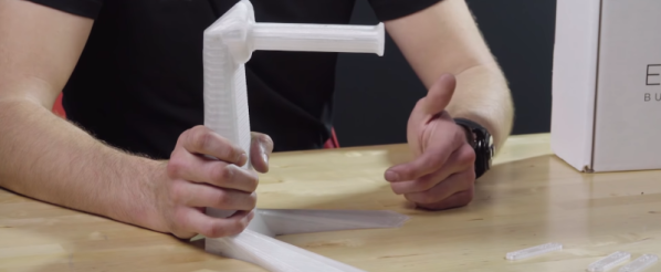
We’re all too familiar with the 3D printing post-processing step of removing supports, and lamenting the waste of plastic on yet another dwindling reel of filament. When the material is expensive NinjaFlex or exotic bio-printers, printing support is downright painful. A group at USC has come up with a novel way of significantly reducing the amount of material that’s 3D printed by raising portions of the bed over time, and it makes us wonder why a simpler version isn’t done regularly.
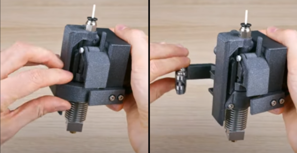
In the USC version, the bed has a bunch of square flat metal pieces, with a metal tube underneath each. The length of the tube determines the eventual height of that square. Before the print is made, the bed is prepared by inserting the appropriate length tubes in the correct squares. Then, during the print, a single motor pushes a platform up, and based on the height of the pin, that portion of the bed raises appropriately, then stops at the right height.
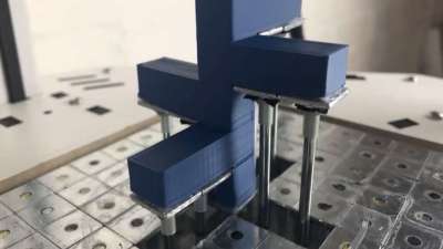 This is a significant savings over having a matrix of linear motors or servos to control each square, at the cost of having to prepare the pins for each print.
But it has us wondering; since CURA and other slicing software have the ability to pause at height, what if the slicing software could allow for the placement of spacer blocks of a known size? The user would have a variety of reusable spacer blocks, and position them in the software, and the slicer would build the support material starting on top of the block. It could print a rectangle on the base layer to aid in proper placement of the blocks during printing, and pause at the correct heights to let the user insert the blocks. At the end of the print a lot less support material has been used.
For situations where you want to leave your print to run unattended, or if the cost of the material is low enough that it doesn’t justify the effort, then maybe this isn’t worth it. Another problem might be heating that platform, though since only support material will be printed on it, some curling won’t matter much. What do you think?
Continue reading “Dynamic Build Platforms For 3D Printers Remove Supports And Save Material” →