Making full use of the capabilities and advantages of 3D printing requires a very different way of thinking compared to more traditional manufacturing methods. Often we see designs that do not really take these advantages into account, so we’re always on the lookout for interesting designs that embrace the nature of 3D-printed parts in interesting ways. [joopjoop]’s spring-loaded PCB vise is one such ingenious design that incorporates the spring action into the print itself.
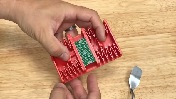
This vise is designed to be printed as a single piece, with very little post-processing required if your printer is dialed in. There is a small gap between the base plate and the springs and clamping surfaces that need to be separated with a painters knife or putty knife. Two “handles” have contours for your fingers to operate the clamping surfaces. It opens quickly for inserting your latest custom PCB.
PLA can be surprisingly flexible if the right geometry is used, and these springs are an excellent example of this. In the video below [Chuck Hellebuyck] does a test and review of the design, and it looks like it works well for hand soldering (though it probably won’t hold up well with a hot air station). Last month our own [Tom Nardi] recently reviewed a similar concept that used spiral springs designed into the printed part. While these both get the job done, [Tom’s] overall verdict is that a design like this rubber-band actuated PCB vise is a better long-term option.
It takes some creativity to get right, but printing complete assemblies as a single part, is a very useful feature of 3D printing. Just be careful of trying to make it the solution for every mechanical problem.