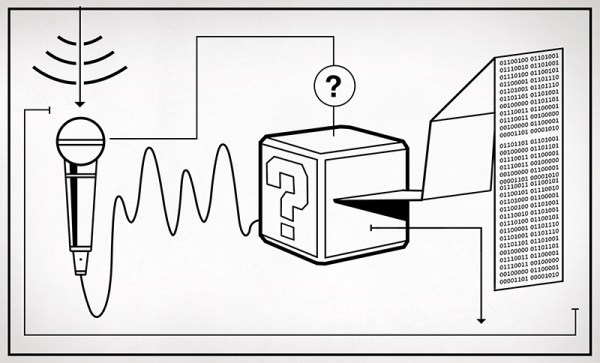
If the first circuit a hacker builds is an LED blinker, the second one has to be a noisemaker of some sort. From simple buzzers to the fabled Atari punk console, and guitar effects to digitizing circuits, hackers, makers and engineers have been building incredible audio projects for decades. This week the Hacklet covers some of the best audio projects on Hackaday.io!
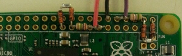
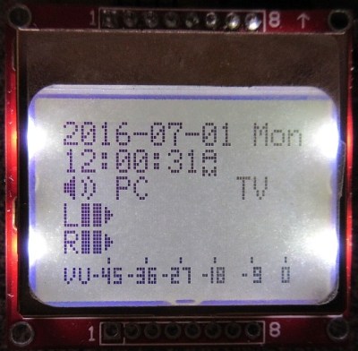 We start with [K.C. Lee] and Automatic audio source switching. Two audio sources, one amplifier and speaker system; this is the problem [K.C. Lee] is facing. He listens to audio from his computer and TV, but doesn’t need to have both connected at the same time. Currently he’s using a DPDT switch to change inputs. Rather than manually flip the switch, [K.C. Lee] created this project to automatically swap sources for him. He’s using an STM32F030F4 ARM processor as the brains of the operation. The ADCs on the microcontroller monitor both sources and pick the currently active one. With all that processing power, and a Nokia LCD as an output, it would be a crime to not add some cool features. The source switcher also displays a spectrum analyzer, a VU meter, date, and time. It even will attenuate loud sources like webpages that start blasting audio.
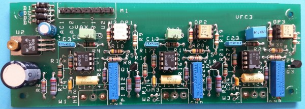
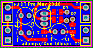 Next up is [Adam Vadala-Roth] with Audio Blox: Experiments in Analog Audio Design. [Adam] has 32 projects and counting up on Hackaday.io. His interests cover everything from LEDs to 3D printing to solar to hydroponics. Audio Blox is a project he uses as his engineer’s notebook for analog audio projects. It is a great way to view a hacker figuring out what works and what doesn’t. His current project is a 4 board modular version of the Big Muff Pi guitar pedal. He’s broken this classic guitar effect down to an input board, a clipping board, a tone control, and an output stage. His PCB layouts, schematics, and explanations are always a treat to view and read!
 Next we have [Paul Stoffregen] with Teensy Audio Library. For those not in the know, [Paul] is the creator of the Teensy family of boards, which started as an Arduino on steroids, and has morphed into something even more powerful. This project documents the audio library [Paul] created for the Freescale/NXP ARM processor which powers the Teensy 3.1. Multiple audio files playing at once, delays, and effects, are just a few things this library can do. If you’re new to the audio library, definitely check out [Paul’s] companion project
Microcontroller Audio Workshop & HaD Supercon 2015. This project is an online version of the workshop [Paul] ran at the 2015 Hackaday Supercon in San Francisco.
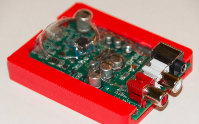 Finally we have [drewrisinger] with DrDAC USB Audio DAC. DrDac is a high quality DAC board which provides a USB powered audio output for any PC. Computers these days are built down to a price. This means that lower quality audio components are often used. Couple this with the fact that computers are an electrically noisy place, and you get less than stellar audio. Good enough for the masses, but not quite up to par if you want to listen to studio quality audio. DrDAC houses a PCM2706 audio DAC and quality support components in a 3D printed case. DrDAC was inspired by [cobaltmute’s] pupDAC.
If you want to see more audio projects and hacks, check out our new audio projects list. See a project I might have missed? Don’t be shy, just drop me a message on Hackaday.io. That’s it for this week’s Hacklet, As always, see you next week. Same hack time, same hack channel, bringing you the best of Hackaday.io!