A Repeater For WWVB

For those living in the continental US who, for whatever reason, don’t have access to an NTP server or a GPS device, the next best way to make sure the correct time is known is with the WWVB radio signal. Transmitting out of Colorado, the 60-bit 1 Hz signal reaches all 48 states in the low-frequency band and is a great way to get a clock within a few hundred nanoseconds of the official time. But in high noise situations, particularly on the coasts or in populated areas these radio-based clocks might miss some of the updates. To keep that from happening [Mike] built a repeater for this radio signal.

The repeater works by offloading most of the radio components to an Arduino. The microcontroller listens to the WWVB signal and re-transmits it at a lower power to the immediate area, in this case no further than a few inches away or enough to synchronize a few wristwatches. But it has a much better antenna for listening to WWVB so this eliminates the (admittedly uncommon) problem of [Mike]’s watches not synchronizing at least once per day. WWVB broadcasts a PWM signal which is easy for an Arduino to duplicate, but this one needed help from a DRV8833 amplifier to generate a meaningfully strong radio signal.

Although there have been other similar projects oriented around the WWVB signal, [Mike]’s goal for this was to improve the range of these projects so it could sync more than a single timekeeping device at a time as well as using parts which are more readily available and which have a higher ease of use. We’d say he’s done a pretty good job here, and his build instructions cover almost everything even the most beginner breadboarders would need to know to duplicate it on their own.

A Modern Version Of Famous, Classic Speaker

Modern musicians may take for granted that a wide array of musical instruments can either be easily connected to a computer or modeled entirely in one, allowing for all kinds of nuanced ways of creating unique sounds and vivid pieces of music without much hardware expense. Not so in the 1930s. Musicians of the time often had to go to great lengths to generate new types of sounds, and one of the most famous of these was the Leslie speaker, known for its unique tremolo and vibrato. Original Leslies could cost thousands now, though, so [Levi Graves] built a modern recreation.

The Leslie speaker itself got its characteristic sound by using two speakers. The top treble speaker was connected to a pair of horns (only one of which produced sound, the other was used for a counterweight) on a rotating platform. The second speaker in the bottom part of the cabinet faced a rotating drum. Both the horns and drum were rotated at a speed chosen by the musician and leading to its unique sound. [Levi] is actually using an original Leslie drum for his recreation but the sound is coming out of a 100-watt “mystery” speaker, with everything packaged neatly into a speaker enclosure. He’s using a single-speed Leslie motor but with a custom-built foot switch can employ more fine-tuned control over the speed that the drum rotates.

Even though modern technology allows us to recreate sounds like this, often the physical manipulation of soundwaves like this created a unique feeling of sound that can’t be replicated in any other way. That’s part of what’s driven the popularity of these speakers throughout the decades, as well as the Hammond organs they’re often paired with. The tone generators on these organs themselves are yet another example of physical hardware providing a unique, classic sound not easily replicated.

Continue reading “A Modern Version Of Famous, Classic Speaker”

Convert A Cheap Tube Preamp Into A Headphone Amp With Jenny

Big-name tube amplifiers often don’t come cheap. Being the preserve of dedicated audiophiles, those delicate hi-fis put their glass components on show to tell you just how pricy they really ought to be. If you just want to dip your toe in the tube world, though, there’s a cheaper and more accessible way to get started. [Jenny List] shows us the way with her neat headphone amp build.

The build starts with an off-the-shelf preamp kit based around two common 6J1 tubes. These Chinese pentode valves come cheap and you can usually get yours hands on this kit for $10 or so. You can use the kit as-is if you just want a pre-amp, but it’s not suitable for headphone use out of the box due to its high-impedance output. That’s where [Jenny] steps in.

You can turn these kits into a pleasing headphone amp with the addition of a few choice components. As per the schematic on Github, a cheap transformer and a handful of passives will get it in the “good enough” range to work. The transformer isn’t perfect, and bass response is a compromise, but it’s a place to start your tinkering journey. Future work from [Jenny] will demonstrate using a MOSFET follower to achieve much the same result.

We’ve seen a great number of headphone amplifiers over the years, including one particularly attractive resin-encased example. Video after the break.

Continue reading “Convert A Cheap Tube Preamp Into A Headphone Amp With Jenny”

Understanding The Miller Effect

As electronics rely more and more on ICs, subtle details about discrete components get lost because we spend less time designing with them. For example, a relay seems like a simple component, but selecting the contact material optimally has a lot of nuance that people often forget. Another case of this is the Miller effect, explained in a recent video by the aptly named [Old Hack EE].

Put simply, the Miller effect — found in 1919 by [John Milton Miller] — is the change in input impedance of an inverting amplifier due to the gain’s effect on the parasitic capacitance between the amplifier’s input and output terminals. The parasitic capacitance acts like there is an additional capacitor in parallel with the parasitic capacitance that is equivalent to the parasitic capacitance multiplied by the gain. Since capacitors in parallel add, the equation for the Miller capacitance is C-AC where C is the parasitic capacitance, and A is the voltage gain which is always negative, so you might prefer to think of this as C+|A|C.

Continue reading “Understanding The Miller Effect”

Building An Automotive Load Dump Tester

For those who have not dealt with the automotive side of electronics before, it comes as somewhat of a shock when you find out just how much extra you have to think about and how tough the testing and acceptance standards are. One particular test requirement is known as the “load dump” test. [Tim Williams] needed to build a device (first article of three) to apply such test conditions and wanted to do it as an exercise using scrap and spares. Following is a proper demonstration of follow-through from an analytical look at the testing specs to some interesting hand construction.

Manhattan-style layout

The load dump test simulates the effect of a spinning automotive alternator in a sudden no-load scenario, such as a loose battery terminal. The sudden reduction in load (since the battery no longer takes charging current) coupled with the inductance of the alternator windings causes a sudden huge voltage spike. The automotive standard ISO 7637-2:2011 dictates how this pulse should be designed and what load the testing device must drive.

The first article covers the required pulse shape and two possible driving techniques. It then dives deep into a case study of the Linear Tech DC1950A load dump tester, which is a tricky circuit to understand, so [Tim] breaks it down into a spice model based around a virtual transistor driving an RC network to emulate the pulse shape and power characteristics and help pin down the specs of the parts needed. The second article deals with analysing and designing a hysteric controller based around a simple current regulator, which controls the current through a power inductor. Roughly speaking, this circuit operates a bit like a buck converter with a catch diode circulating current in a tank LC circuit. A sense resistor in the output path is used to feedback a voltage, which is then used to control the driving pulses to the power MOSFET stage. [Tim] does a good job modeling and explaining some of the details that need to be considered with such a circuit.

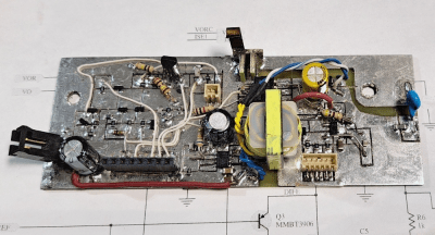
Continue reading “Building An Automotive Load Dump Tester”

Mechanical Logic Gates With Amplification

One of the hardest things about studying electricity, and by extension electronics, is that you generally can’t touch or see anything directly, and if you can you’re generally having a pretty bad day. For teaching something that’s almost always invisible, educators have come up with a number of analogies for helping students understand the inner workings of this mysterious phenomenon like the water analogy or mechanical analogs to electronic circuits. One of [Thomas]’s problems with most of these devices, though, is that they don’t have any amplification or “fan-out” capability like a real electronic circuit would. He’s solved that with a unique mechanical amplifier.

Digital logic circuits generally have input power and ground connections in addition to their logic connection points, so [Thomas]’s main breakthrough here is that the mechanical equivalent should as well. His uses a motor driving a shaft with a set of pulleys, each of which has a fixed string wrapped around the pulley. That string is attached to a second string which is controlled by an input. When the input is moved the string on the pulley moves as well but the pulley adds a considerable amount of power to to the output which can eventually be used to drive a much larger number of inputs. In electronics, the ability to drive a certain number of inputs from a single output is called “fan-out” and this device has an equivalent fan-out of around 10, meaning each output can drive ten inputs.

[Thomas] calls his invention capstan lever logic, presumably named after a type of winch used on sailing vessels. In this case, the capstan is the driven pulley system. The linked video shows him creating a number of equivalent circuits starting with an inverter and working his way up to a half adder and an RS flip-flop. While the amplifier pulley does take a minute to wrap one’s mind around, it really helps make the equivalent electronic circuit more intuitive. We’ve seen similar builds before as well which use pulleys to demonstrate electronic circuits, but in a slightly different manner than this build does.

Continue reading “Mechanical Logic Gates With Amplification”

Particle Physics On A Small, Affordable PCB

Experimenting in the world of particle physics probably brings to mind large, expensive pieces of equipment like particle accelerators, or at least exotic elements or isotopes that most of us can’t easily find. But plenty of common objects emit various particles, and it turns out that detecting these particles does not require government backing or acres of test equipment. In fact, you can get this job done with a few readily-available parts and [Tim] shows us how it’s done with his latest project.

The goal of his build is to have a working particle detector for less than $10 per board, although he’s making them in bulk to be used in an educational setting. The board uses a set of photodiodes enclosed in a protective PCB sandwich to detect beta particles from a Potassium-40 source. The high-energy electron interacts with the semiconductor in the photodiode and creates a measurable voltage pulse, which can be detected and recorded by the microcontroller on the board. For this build an RP2040 chip is being used, with a number of layers of amplification between it and the photodetector array used to get signals that the microcontroller can read.

Getting particle physics equipment into the hands of citizen scientists is becoming a lot more common thanks to builds like this which leverage the quirks of semiconductors to do something slightly outside their normal use case, and of course the people building them releasing their projects’ documentation on GitHub. We’ve also seen an interesting muon detector with a price tag of around $100 and an alpha particle detector which uses a copper wire with a high voltage to do its work.