“What Is My Purpose?” You Amplify And Display Signals.

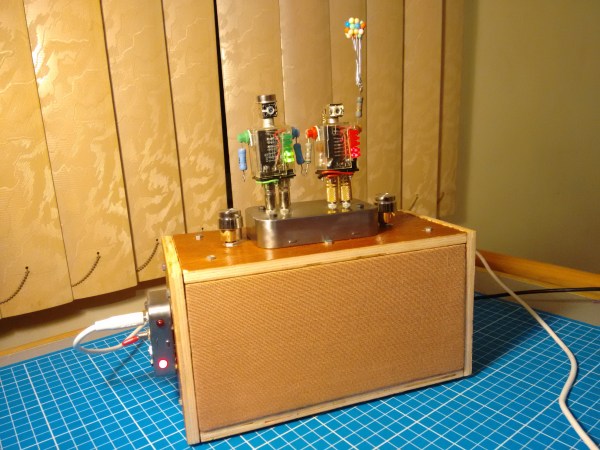
[Andy_Fuentes22] likes to stream music, but is (understandably) underwhelmed by the sound that comes out of his phone. He wanted to build something that not only looks good, but sounds good. Something that could stream music through a Chromecast or a Raspi, but also take auxiliary input. Something awesome, like the Junkbots Sound System.

The ‘bots, named LR-E (Larry) and R8-CHL (Rachel), aren’t just cool pieces of art. They’re both dead-bug-walking bots with an LM386-based amplifier circuit and an AN6884-based VU meter in their transparent, industrial relay bodies. LR-E is the left channel, and his lovely wife is the right channel. The best part is that they are wired into the circuit through their 3.5mm plug legs and the corresponding jacks mounted in the Altoids tin base.

[Andy] built this labor of love from the ground up. He started with some very nice design sketches and took a bazillion pictures along the way. We think it sounds pretty good, but you can judge for yourself after the break. If VU meters are your jam, here’s another that’s built into the speaker.

Continue reading ““What Is My Purpose?” You Amplify And Display Signals.”

You Can Have My LM386s When You Pry Them From My Cold Dead Hands

Everyone has a chip-of-shame: it’s the part that you know is suboptimal but you keep using it anyway because it just works well enough. Maybe it’s not what you would put into a design that you’re building more than a couple of, but for a quick and dirty lashup, it’s just the ticket. For Hackaday’s [Adam Fabio], that chip is the TIP120 transistor. Truth be told, we have more than one chip of shame, but for audio amplification purposes, it’s the LM386.

The LM386 is an old design, and requires a few supporting passive components to get its best performance, but it’s fundamentally solid. It’s not noise-free and doesn’t run on 3.3 V, but if you can fit a 9 V battery into your project and you need to push a moderate amount of sound out of a speaker, we’ll show you how to get the job done with an LM386.

Continue reading “You Can Have My LM386s When You Pry Them From My Cold Dead Hands”

Simple Hearing Amplifier

Hearing aids are probably more high-tech than you think. They are tiny. They have to go through a lot of trouble to prevent feedback. They need a long battery life. The good ones match their amplification to the inverse of your hearing loss (amplifying only the bands where you don’t hear as well).

[NotionSunday] put together a hearing amplifier project that probably doesn’t hit many of those design criteria. However, thanks to a 3D printed case, it looks pretty good. The device uses a dual opamp to boost the output from two microphones and feeds it to a conventional headphone.

Continue reading “Simple Hearing Amplifier”

Sending music long distance using laser

Sending Music Long Distance Using A Laser

This isn’t the first time we’ve seen DIYers sending music over a laser beam but the brothers [Armand] and [Victor] are certainly in contention for sending the music the longest distance, 452 meter/1480 feet from their building, over the tops of a few houses, through a treetop and into a friend’s apartment. The received sound quality is pretty amazing too.

In case you’ve never encountered this before, the light of the laser is modulated with a signal directly from the audio source, making it an analog transmission. The laser is a 250mW diode laser bought from eBay. It’s powered through a 5 volt 7805 voltage regulator fed by a 12V battery. The signal from the sound source enters the circuit through a step-up transformer, isolating it so that no DC from the source enters. The laser’s side of the transformer feeds the base of a transistor. They included a switch so that the current from the regulator can either go through the collector and emitter of the transistor that’s controlled by the sound source, giving a strong modulation, or the current can go directly to the laser while modulation is provided through just the transistor’s base and emitter. The schematic for the circuit is given at the end of their video, which you can see after the break.

They receive the beam in their friend’s apartment using solar cells, which then feed a fairly big amplifier and speakers. From the video you can hear the surprisingly high quality sounds that results. So check it out. It also includes a little Benny Hill humor.

Continue reading “Sending Music Long Distance Using A Laser”

“Nixie” Tubes Sound Good

A tube is a tube is a tube. If one side emits electrons, another collects them, and a further terminal can block them, you just know that someone’s going to use it as an amplifier. And so when [Asa] had a bunch of odd Russian Numitron tubes on hand, an amplifier was pretty much a foregone conclusion.

A Numitron is a “low-voltage Nixie”, or more correctly a single-digit VFD in a Nixiesque form factor. So you could quibble that there’s nothing new here. But if you dig into the PDF writeup, you’ll find that the tubes have been very nicely characterised, situating this project halfway between dirty hack and quality lab work.

It’s been a while since we’ve run a VFD-based amplifier project, but it’s by no means the first time. Indeed, we seem to run one every couple years. For instance, here is a writeup from 2010, and the next in 2013. Extrapolating forward, you’re going to have to wait until 2019 before you see this topic again.

Circuit Design? Spread The Joy

Accountants and MBAs use spreadsheets to play “what if” scenarios with business and financial data. Can you do the same thing with electronic circuits? The answer–perhaps not surprisingly–is yes.

Consider this simple common emitter amplifier (I modeled it in PartSim, if you’d like to open it):

In this particular case, there are several key design parameters. The beta of the transistor (current gain) is 220. The amplifier has an overall voltage gain of about 3 (30/10). I say about, because unless the transistor is ideal, it won’t be quite that. The supply voltage (Vcc) is 12 volts and I wanted the collector voltage (VC) to idle at 6V to allow the maximum possible positive and negative swing. I wanted the collector current (IC) to be 200mA.

Continue reading “Circuit Design? Spread The Joy”

Building Better Tube Amps With Heathkit Parts

[Justin] had been trying to find a good tube amp for years, but all the best examples were either expensive or a complete basket case. Instead of buying a vintage stereo tube amp, he decided to build his own using the guts of a Heathkit AA-100, a popular tube amp from the 60s and 70s that doesn’t have a great reputation for sound quality.

This project was based on an earlier project from a decade ago that replicated the very popular Dynaco ST-70 tube amp from parts taken from the Heathkit AA-100. The schematic for this conversion was readily available on the usual tube head message boards, and a few PCBs were available for the input stage.

With the schematic in hand, the next thing for [Justin] to do was get a nice enclosure. High quality tube amps are valued as much for their appearance as they are for their sound quality, and after giving his father-in-law a few sketches, a cherry hardwood chassis stained in a beautiful golden brown appeared on [Justin]’s workbench.

The big iron for this new tube amp was taken directly from the old Heathkit, and a few hours in front of a mill netted [Justin] a chassis panel drilled out for the transformers and tube sockets. The rest of the project was a bit of assembly, point-to-point wiring, and wire management giving [Justin] a fantastic amplifier that will last for another fifty years until someone decides to reuse the transformers.