Arduino Magnetic Board Is Anything But Boring

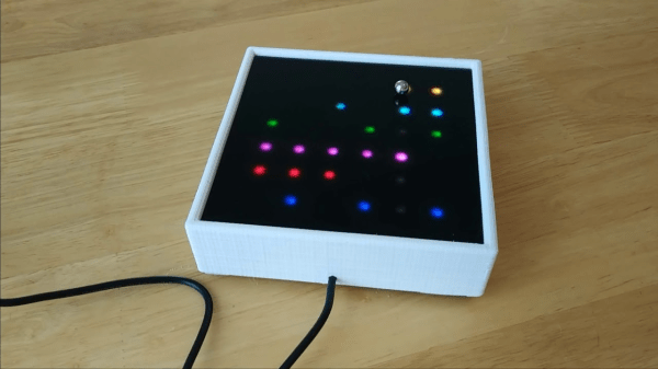
Magnets (especially those ball magnets!) are endlessly fascinating, aren’t they? It’s almost dangerous to combine them with LEDs, because how are you supposed to get anything done with something like [andrei.erdei]’s Arduino Magnetic Board beckoning from beyond your keyboard?

This tons-of-fun board uses ball magnets to light up RGB LEDs as they roll around on the sexy Plexiglas field. Underneath the LED matrix is an orchestra of 36 reed switches — those little glass gas-filled grains of rice with axial leads that snap together or fly apart in the presence of magnetic fields. The LEDs are controlled with an Arduino Pro Mini, and so is the 8Ω speaker for sound effects.

[andrei.erdei] has already developed a few applications for this delightful desk toy, and they’re all on GitHub. There’s a chase game that involves tilting the board to catch the next red dot with the magnet, a light painting game, and a sequencer that mimics the ToneMatrix. Roll past the break to check out the series of short demo videos.

Want to play with reed switches but can’t source any at the moment? You could just make them yourself.

Continue reading “Arduino Magnetic Board Is Anything But Boring”

Subwoofer Gets Arduino Brain Transplant

The Samsung PS-WTX500 subwoofer is designed to be used as part of a 5.1 channel home theater system, but not just any system. It contains the amplifiers for all the channels, but they’ll only function when the subwoofer is connected to the matching receiver. [Alejandro Zarate] figured there must be some way to unlock the system’s full functionality without being limited to the original receiver, he just needed to reverse engineer how the subwoofer worked.

All the wires tuck underneath the Arduino

The result is a fantastically well documented write-up that covers the whole process, starting with how [Alejandro] identified and researched the Pulsus PS9829B Digital Audio Processor (DAP). Documentation for this particular chip seems hard to come by, but he was able to find a similar chip from the same manufacturer that was close enough to put him on the right track. From there, he started studying the SPI communications between the DAP and the subwoofer’s S3P70F4 microcontroller.

After analyzing the communication between the two chips, [Alejandro] pulled the S3P70F4 off the board and wired an Arduino Pro Mini 328 in its place. The Arduino was quite a bit larger than the original microcontroller, but with some careful wiring, he manged a very professional looking installation. Short of coming up with a custom PCB adapter, we don’t think it could look much better.

With some relatively straightforward code and a listing of the captured byte sequences, the Arduino was able to power up the PS-WTX500’s amplifiers and handle the incoming audio signal as a stand-alone device.

In the past we’ve seen a similar trick done with the ESP8266, which had the added benefit of enabling WiFi control of the speakers. We’re all for adding modern functionality to older hardware, even if you’ve got to hang it off the back as an external module.

Continue reading “Subwoofer Gets Arduino Brain Transplant”

Game On With These Open Source Arduino Buzzers

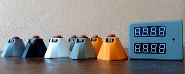
Planning a game of Hacker Jeopardy at your next meetup? You’re going to want some proper buzzers to complete the experience, but why buy when you can build? [Flute Systems] has released an open source DIY game buzzer system based on the Arduino that will help instantly elevate your game. Certainly beats just yelling across the room.

The design has been made to be as easily replicable as possible: as long as you’ve got access to a 3D printer to run off the enclosures for the buzzers and base station, you’ll be able to follow along no problem. The rest of the project consists of modular components put together with jumper wires and scraps of perfboard. Granted it might not be the most elegant solution, but there’s something to be said for projects that beginners and old salts alike can complete.

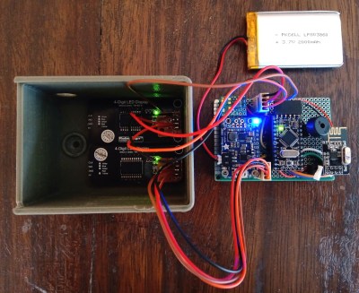
Each buzzer consists of an Arduino Pro Mini 3.3 V, a nRF24L01, and of course a big pushbutton on the top. Each one is powered by a 110 mAh 3.7 V LiPo battery, though [Flute Systems] notes that the current version of the buzzer can’t actually recharge it. You’ll need to pull the pack out and charge it manually once and awhile. Thankfully, the printed enclosure features a very clever twist-lock mechanism which makes it easy to open anytime you need to poke at the internals.

The base station uses the 5 V version of the Pro Mini, with a Adafruit PowerBoost 1000C to step up the voltage from its 2,000 mAh battery. Of course it also has a nRF24L01, and also adds a buzzer and twin four digit seven-segment LED displays. [Flute Systems] says you can expect about five hours of runtime for the base station.

An especially nice feature of this setup is that the eight digit display allows the base station to show the number of each button in the order it was received. So rather than just getting a display of who buzzed in first, you can see the chronological order in which all eight buttons were pressed. Coming up with clever applications for this capability is left as an exercise for the reader.

Of course, there’s more than one way to build a buzzer. If you don’t like the way [Flute Systems] did it, then check out this version that uses 900 MHz radios and an OLED to show the results.

A Custom Built FPV Monitor To Keep The Fans Happy

If you’re going to be flying around a FPV-capable aircraft, be it a quadcopter or a fixed-wing plane, you shouldn’t be surprised if bystanders want to take a turn wearing your googles. Of course we hope that you’re good enough flying line of sight that you don’t need to be wearing the googles to stay airborne, but it does make it harder to pull off the sort of tricks and maneuvers that your audience wants to see. So if you want to put on a good show, the audience really needs their own display.

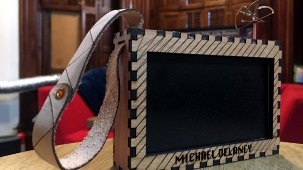
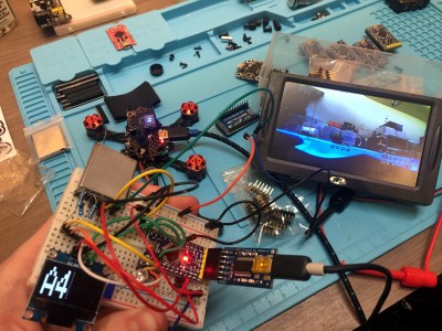
Unfortunately, as avid FPV flier [Michael Delaney] discovered, even the “cheap” ones will run you at least $100 USD. So he did what any self-respecting hacker would do, he set out to build his own. Using a collection of off the shelf components he was able to build a very impressive monitor that lets the viewer see through the eyes of his quadcopter at less than half the cost of commercially available offerings. Though even if he hadn’t manged to beat the cost of a turn-key monitor, we think it would have been more than worth it for this piece of highly customized gear.

At the heart of the monitor is a Boscam RX5808 5.8 GHz receiver, which is controlled by an Arduino Pro Mini. The video output from the receiver is sent to a 4.2″ TFT screen intended for the Raspberry Pi, and on the backside of the laser-cut wooden enclosure there’s a 128 x 64 I2C OLED to display the currently selected channel and diagnostic information.

An especially nice touch for this project is the custom PCB used to tie all the components together. [Michael] could have taken the easy route and sent the design out for fabrication, but instead went with the traditional method of etching his own board in acid. Though he did modernize the process a bit by using a laser and pre-sensitized copper clad board, a method that seems to be gaining in popularity as laser engravers become a more common component of the hacker’s arsenal.

We’ve previously covered using the RX5808 and Arduino combo to create a spectrum analyzer, in case you want to do more than just watch your friends do powerloops.

Look Upon Eyepot, And Weep For Mercy

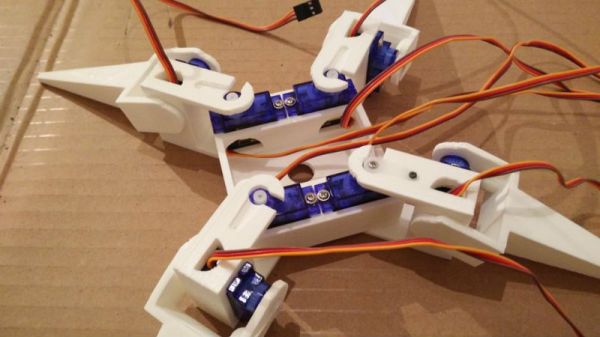
Hope you weren’t looking forward to a night of sleep untroubled by nightmares. Doing his part to make sure Lovecraftian mechanized horrors have lease in your subconscious, [Paul-Louis Ageneau] has recently unleashed the horror that is Eyepot upon an unsuspecting world. This Cycloptic four legged robotic teapot takes inspiration from an enemy in the game Alice: Madness Returns, and seems to exist for no reason other than to creep people out.

Even if you aren’t physically manifesting nightmares, there’s plenty to learn from this project. [Paul-Louis Ageneau] has done a fantastic job of documenting the build, from the OpenSCAD-designed 3D printed components to the Raspberry Pi Zero and Arduino Pro Mini combo that control the eight servos in the legs. If you want to play along at home all the information and code is here, though feel free to skip the whole teapot with an eyeball thing.

A second post explains how the code is written for both the Arduino and Pi, making for some very illuminating reading. A Python script on the Pi breaks down the kinematics and passes on the appropriate servo angles to the Arduino over a serial link. Combined with a web interface for control and a stream from the teapot’s Raspberry Pi Camera module, and you’ve got the makings of the world’s creepiest telepresence robot. We’d love to see this one stomping up and down a boardroom table.

Seems we are on a roll recently with creepy robot pals. Seeing a collaboration between Eyepot and JARVIS might be too much for us to handle. Though we have a pretty good idea how we’d want to control them.

Designing a mini spy bug recorder

Mini Spy Bug Walkthrough

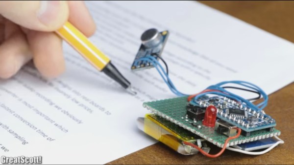
What we like most about [GreatScott’s] project videos is that he not only shows making them but also the calculations for selecting parts and the modifications along the way. This time he’s made a mini spy bug that records up to nine hours of audio.

His first task was to figure out if the ATmega328p’s ADC is suitable for audio sampling, but only after he explains how sampling works by periodically checking the input voltage from the microphone. Checking the datasheet he found that the ADC’s fastest conversion time is 13 microseconds, which works out to a sampling rate of 76.923 kHz. Good enough.

He then walks through why and how he decided to go with a pre-made amplifier circuit built around the MAX9814 IC. Spoiler alert. His electret’s amplifier output voltage was too low, using an off-the-shelf circuit instead of making his own kept things simple, and the circuit has automatic gain control.

At this point, he added the MicroSD card adapter. Why not just transmit the audio over FM as so many others have done with their hacks? Perhaps he’s worried about someone detecting the transmission and finding his bug.

His final optimization involved getting a good battery life. He measured the circuit’s current draw at 20 milliamps. With a 160 mAh battery capacity, that would be 8 hours of recording time. Removing the Arduino Pro Mini’s voltage regulator and two LEDs got the current down to 18 milliamps and a recording time of 9 hours. Better.

Those are the highlights. Enjoy his full walkthrough in the video below.

Continue reading “Mini Spy Bug Walkthrough”

Sub-$20 Arduino-Based Telemetry System

[William Osman] set out to prove that unlike expensive commercial data logging rigs, he could get the same results for under twenty bucks. He wanted to build a wireless three-axis accelerometer for a race car project, allowing engineers to make modifications to the suspension based on the data collected.

The hardware consists of an Arduino Pro Mini connected to a three-axis accelerometer, and an nRF24L01 wireless module. Power is supplied by the race car’s 12 V, changed to 5 V by a linear regulator with the Pro Mini in turn supplying 3.3 V. The base station consists of an Arduino and another nRF24L01 module plugged into a laptop.

The telemetry system is based on COSMOS, an open-source, realtime datalogging platform put out by Bell Aerospace. COSMOS consists of fifteen separate applications depending on how you want to view and manage your telemetry. You can download [William]’s COSMOS config files and Arduino sketch on Google Docs.

We’ve published a bunch of pieces on telemetry, like this ESP8266 telemetry project, a rocket telemetry rig, and open sourcing satellite telemetry.

[Thanks, Dennis Nestor!]