If there’s a happier word ever imported into the English language than “Glockenspiel”, we’re not sure what it is. And controlling said instrument with a bunch of servos and an Arduino makes us just as happy.
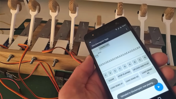
When [Leon van den Beukel] found a toy glockenspiel in a thrift store, he knew what had to be done – Arduinofy it. His first attempt was a single hammer on a pair of gimballed servos, which worked except for the poor sound quality coming from the well-loved toy. The fact that only one note at a time was possible was probably the inspiration for version two, which saw the tone bars removed from the original base, cleaned of their somewhat garish paint, and affixed to a new soundboard. The improved instrument was then outfitted with eight servos, one for each note, each with a 3D-printed arm and wooden mallet. An Arduino runs the servos, and an Android app controls the instrument via Bluetooth, because who doesn’t want to control an electronic glockenspiel with a smartphone app? The video below shows that it works pretty well, even if a few notes need some adjustment. And we don’t even find the servo noise that distracting.
True, we’ve featured somewhat more accomplished robotic glockenspielists before, but this build’s simplicity has a charm of its own.
Continue reading “Well-Loved Toy Turned Into Robotic Glockenspiel”