[psgarcha] took a year-old Arduino Uno on an international trip and upon returning found something was wrong. Every time he would try to upload, he would get the dreaded avrdude error, ‘stk500_getsync(): not in sync resp=0x00’. The Rx light would blink a few times during the attempted upload, but the tx light did not. Somehow, something was terribly wrong with the ‘duino, and [psgarcha] dug deep to figure out why.
To test the quality of the Arduino’s serial connection, [psgarcha] performed a loopback test; basically a wire plugged into the Tx and Rx pins of the Arduino. Sending a short message through the serial port showed the problem wasn’t the USB cable, the ATmega16u2 on the ‘duino, or any traces on the board. This would require more thought.
The main reason for the error would then be no communication between the computer and the ‘duino, the wrong COM port selected, the wrong board selected in the Arduino text editor, or timing errors or a corrupt bootloader. The first three errors were now out of the question, leaving timing errors and a corrupt bootloader. Troubleshooting then moved on to ordering a new programmer, and still this didn’t work with the broken Uno.
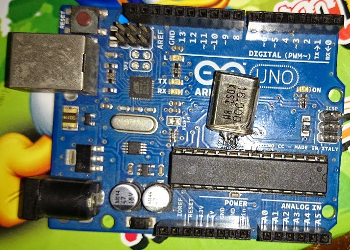
Frustrated with one of the greatest failures to become an Arduino tinkerer, [psgarcha] took a good, long look at the Uno board. He glanced over to an Arduino Mega board. Something looked different. On the Uno, the resonator had blown off. Problem found, at least.
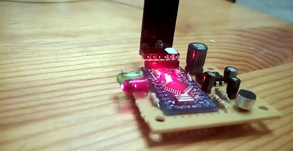
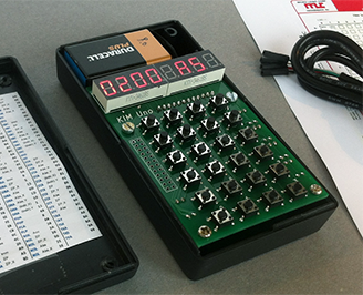
Replacing the blown part with a hilariously large can crystal oscillator, [psgarcha] was back in business. This isn’t how you would fix 99% of getsync() errors, and it’s difficult imagining a situation where a this part would randomly blow, but if you’re ever looking at a nearly intractable problem, you need to start looking at what really shouldn’t fail.
Awesome rework, though.