Remember back in the early-to-mid 2000s when pretty much every cheap USB keyboard you could find started including an abundance of media keys in its layout? Nowadays, especially if you have a customized or reduced-sized mechanical keyboard, those are nowhere to be seen. Whenever our modern selves need those extra keys, we have to turn to external peripherals, and [Gary’s] Knobo is one that looks like it could’ve come straight out of a fancy retail package.
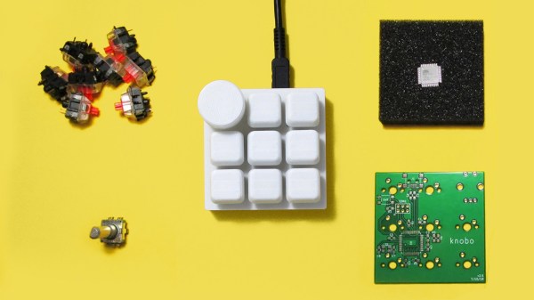
The Knobo is a small macro keypad with 8 mechanical Cherry-style keys and a clickable rotary encoder knob as its main feature. Each key and knob gesture can be customized to any macro, and with five gestures possible with the knob, that gives you a total of thirteen inputs. On top of that, the build and presentation look so sleek and clean we’d swear this was a product straight off of Teenage Engineering’s money-printing machine.
The actions you can do with those inputs range from simple media controls with a volume knob all the way to shortcuts to make a Photoshop artist’s life easier. Right now you can only reprogram the Knobo’s Arduino-based firmware with an In-Circuit Serial Programmer to change what the inputs do, but [Gary] is currently working on configuration software so that users without any programming knowledge will be able to customize it too.
Knobs are just one of those things that everyone wants to use to control their computers, much like giant red buttons. Alternative input devices can range from accessibility-designed to just downright playful. Whatever the inspiration is for them, it’s always nice to see the creativity of these projects.