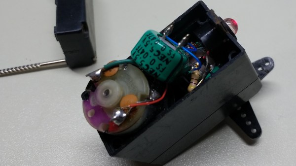
The principle is well understood: use a motor in reverse and you get a generator. Using this bit of knowledge back in 2001 is what kick-started [Ted Yapo]’s Hackaday Prize entry. At the time, [Ted] was searching for a small flashlight for astronomy, but didn’t like dealing with dead batteries. He quickly cobbled together a makeshift solution out of some supercapacitors and a servo-as-a-generator, hacked for continuous rotation.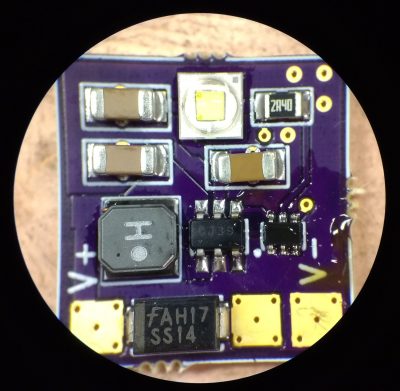
A testament to the supercapacitors, 17 years later it’s still going strong – leading [Ted] to document the project and also improve it. The original circuit was as simple as a servo, protection diode, some supercapacitors, and a LED with accompanying resistor; but now greater things are afoot.
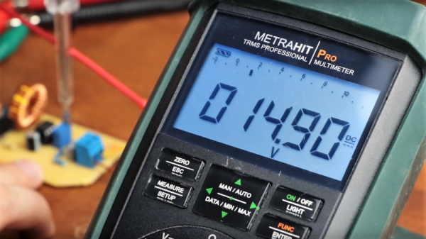
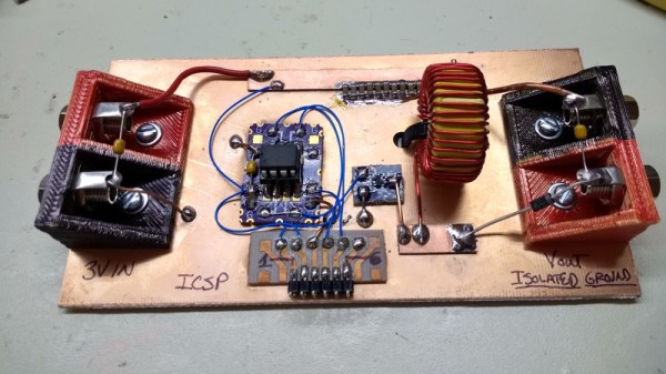
A DC-DC boost converter enables constant power through the LED, regardless of the capacitor voltage. This is achieved by connecting the feedback pin of an MCP1624 switcher to an INA199 current-shunt monitor. The MCP1624 kicks in at 0.65V and stays active down to 0.35V. This is all possible due to the supercapacitors, which happily keep increasing current as voltage drops – all the way to 0.35V. Batteries are less ideal in this situation, as their internal resistance increases as voltage drops, as well as increasing with age.
When testing the new design, [Ted] found that the gears on his servos kept stripping when he was using them to charge capacitors. Though at first he attributed it to the fact that the gears were plastic, he realized that his original prototype from 2001 had been plastic as well. Eventually, he discovered the cause: modern supercapacitors are too good! The ones he’d been using in 2001 were significantly less advanced and had a much higher ESR, limiting the charging current. The only solution is to use metal gear servos
Want to read more about boost converter design? We have the pros and cons of microcontrollers for boost converters, or this neat Nixie driver for USB power.