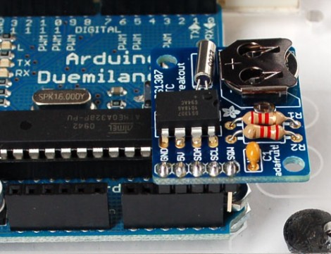
We think of the Arduino as a rapid prototyping tool but we never thought of it as an FTDI breakout board before. [Ihsan Kehribar] wrote a quick post to show how it’s done. You’ll find an FTDI chip on Arduino boards that have a USB connector. It’s used to handle the USB communications on one side, and TTL serial communications on the other. The serial pins from the chip are mapped to the UART on the AVR chip, and in turn they appear on the pin headers for easy connections. Just load up a really simple sketch(available from Ihsan’s post) to make sure the processor doesn’t get in the way and you’ve got yourself an FTDI breakout board. If you happen to have a Seeeduino there’s even more functionality as the board has a selector switch that allows you to choose between 5V and 3.3V levels.
This doesn’t hold true to the newest generation of Arduino, as those board have replaced the FTDI chip with an ATmega8U2. That’s basically and ATmega8 with native USB handling… fancy.
[Thanks Marcus]


