Typically, when most of us need a motor, we jump online to order one from a catalogue. [Levi Janssen] recently had to build his own for a college project, however, and learned a lot along the way.
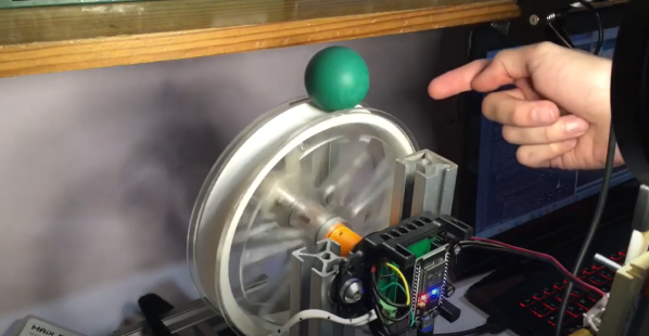
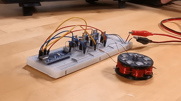
[Levi] whipped up his brushless DC motor design in OnShape. The motor has six coils in the stator, with the rotor carrying eight neodymium magnets. It’s an axial flux design, with the rotor’s magnets sitting above the coils. This makes construction very easy using 3D printed components. Axial flux motors also have benefits when it comes to power density and cooling, though optimization is outside the scope of [Levi]’s work here.
[Levi]’s video covers both the development of the motor itself as well as the drive circuit, too. The latter is of key value if you’re interested in the vagaries of driving these motors, which is far more complex than running a simple brushed motor. He even gets his motor up to 12,500 rpm with his homebrewed drive circuit.
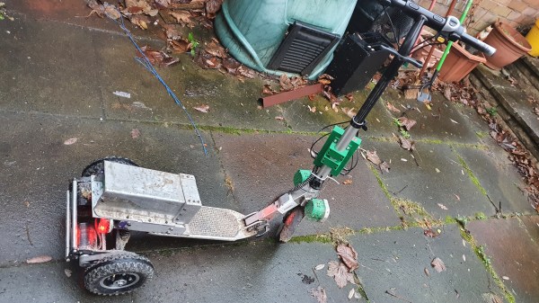
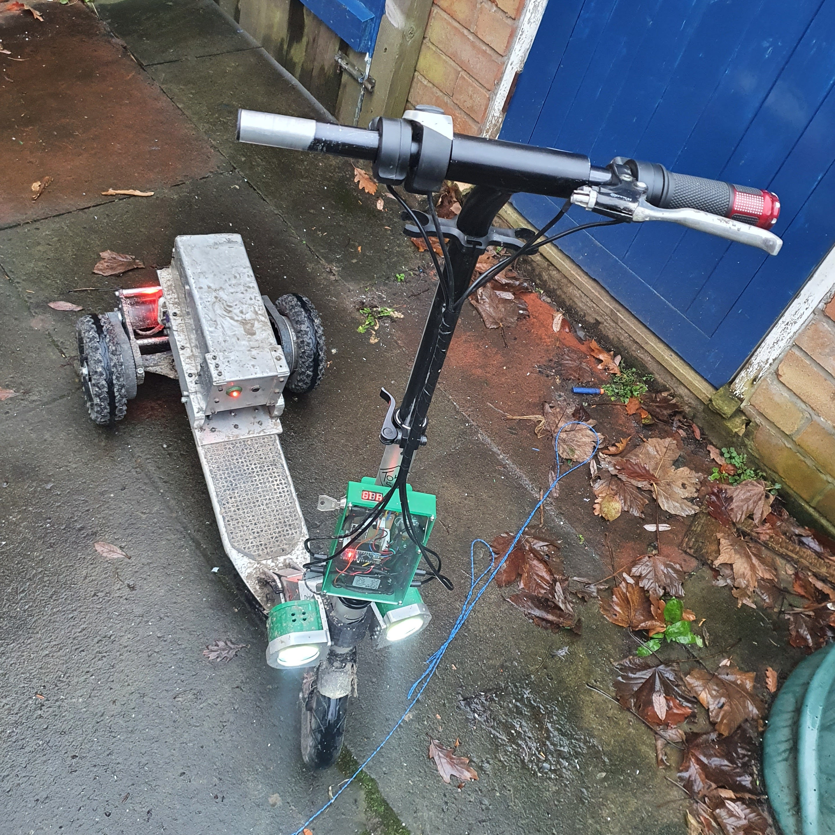
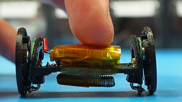
Making your own motors can help you solve some difficult engineering challenges, like building motorized rollerblades. Alternatively, if winding coils sounds too slow and too hard, you can just use off-the-shelf gear and hack it to make it work. Here, we support both methods.
Continue reading “You Can 3D Print A 12,500 RPM Brushless Motor”