Calibration cubes have long been a staple for testing and adjusting 3D printers, but according to [Stefan] of CNC Kitchen, they’re not just ineffective—they could be leading us astray. In the video after the break he explains his reasoning for this controversial claim, and provides a viable alternative.
Such cubes are often used to calibrate the steps per millimeter for the printer’s steppers, but the actual dimensions of said cube can be impacted by over or under extrusion, in addition to how far the machine might be out of alignment. This can be further exacerbated by measuring errors due to elephant’s foot, over extruded corners, or just inaccuracies in the caliper. All these potential errors which can go unnoticed in the small 20 x 20 mm cube, while still leading to significant dimensional errors in larger prints
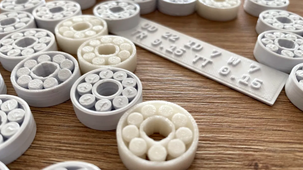
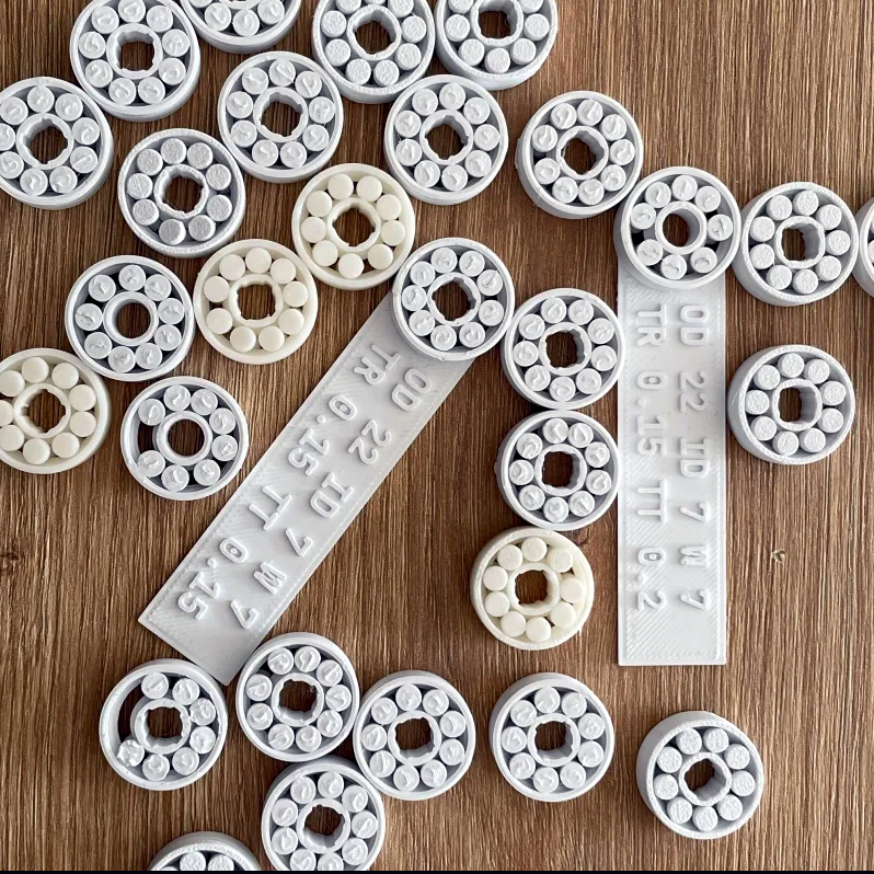
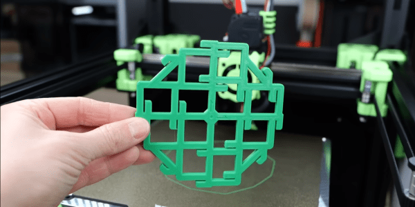
So what’s the solution? Not another cube. It’s something called the “CaliFlower” from [Adam] of Vector 3D. This is not a typical calibration model — it’s carefully designed to minimize measurement errors with ten internal and external measuring points with stops for your calipers. The model costs $5, but for your money you get a complete guide and spreadsheet to calculate the required of corrections needed in your firmware or slicer settings.
If you regularly switch materials in your 3D printer, [Stefan] also advises against adjusting steps per millimeter and suggests defining a scaling factor for each material type instead. With this method validated across different materials like PLA, PETG, ABS, and ASA, it becomes evident that material shrinkage plays a significant role in dimensional inaccuracy, not just machine error. While [Stefan] makes a convincing case against the standard calibration cube for dimensional calibration, he notes that is is still useful for evaluating general print quality and settings.
[Stefan] has always done rigorous testing to back his claims, and this video was no different. He has also tested the effects of filament color on part strength, the practicality of annealing parts in salt, and even printing custom filament.