Laser cutters and 3D printers are game-changing tools to have in the workshop. They make rapid prototyping or repairs to existing projects a breeze as they can churn out new parts with high precision in a very short amount of time. The flip side of that, though, is that they can require quite a bit of maintenance. [Timo] has learned this lesson over his years-long saga owning a laser cutter, although he has attempted to remedy most of the problems on his own, this time by building a Z-axis table on his own rather than buying an expensive commercial offering.
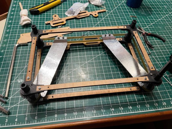
The Z-axis table is especially important for lasers because a precise distance from the lens to the workpiece is needed to ensure the beams’s focal point is correctly positioned. Ensuring this distance is uniform over the entire bed can be a project all on its own. For this build, [Timo] started by building a simple table that allowed all four corners to be adjusted, but quickly moved on to a belt-driven solution that uses a stepper motor in order to adjust the entire workspace. The key to the build was learning about his specific laser’s focal distance which he found experimentally by cutting a slot in an angled piece of wood and measuring the height where the cut was the cleanest.
After everything was built, [Timo] ended up with a Z-axis table that is easily adjustable to the specific height required by his laser. Having a laser cutter on hand to bootstrap this project definitely helped, and it also seems to be an improvement on any of the commercial offerings as well. This also illustrates a specific example of how a laser cutter may be among the best tools for prototyping parts and building one-off or custom tools of any sort.