Your Multimeter Might Be Lying To You

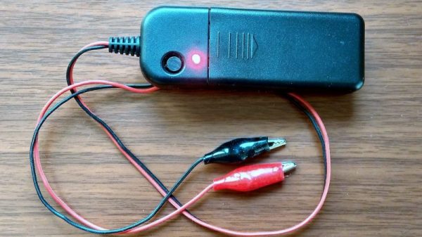
Multimeters are indispensable tools when working on electronics. It’s almost impossible to build any but the most basic of circuits without one to test and troubleshoot potential issues, and they make possible a large array of measurement capabilities that are not easily performed otherwise. But when things start getting a little more complex it’s important to know their limitations, specifically around what they will tell you about circuits designed for high frequency. [watersstanton] explains in this video while troubleshooting an antenna circuit for ham radio.

The issue that often confuses people new to radio or other high-frequency projects revolves around the continuity testing function found on most multimeters. While useful for testing wiring and making sure connections are solid, they typically only test using DC. When applying AC to the same circuits, inductors start to offer higher impedance and capacitors lower impedance, up to the point that they become open and short circuits respectively. The same happens to transformers, but can also most antennas which often look like short circuits to ground at DC but can offer just enough impedance at their designed frequency to efficiently resonate and send out radio waves.

This can give some confusing readings, such as when testing to make sure that a RF connector isn’t shorted out after soldering it to a coaxial cable for example. If an antenna is connected to the other side, it’s possible a meter will show a short at DC which might indicate a flaw in the soldering of the connector if the user isn’t mindful of this high-frequency impedance. We actually featured a unique antenna design recently that’s built entirely on a PCB that would show this DC short but behaves surprisingly well when sending out WiFi signals.

Continue reading “Your Multimeter Might Be Lying To You”

Peer-Reviewed Continuity Tester

One of the core features of the scientific community is the concept of “peer review” where any claims made by a scientist are open to be analyzed and reproduced by others in the community for independent verification. This leads to either rejection of ideas which can’t be reproduced, or strengthening of those ideas when they are. In this community we typically only feature the first step of this process, the original projects from various builders, but we don’t often see someone taking those instructions and “peer reviewing” someone’s build. This is one of those rare cases.

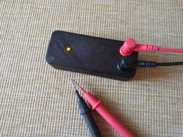
[oxullo] came across [Leo]’s original build for the ultimate continuity tester. This design is much more sensitive than the function which is built in to most multi-meters, and when building this tool specifically some other refinements can be built in as well. [oxullo] began by starting with the original designs, but made several small modifications. Most of these were changing to surface-mount parts, and switching some components for ones already available. Even then, there was still a mistake in the PCB which was eventually corrected. The case for this build is also 3D printed instead of being made out of metal, and with the original video to work from the rest fell into place easily.

[oxullo] is getting comparable results with this continuity tester, so we can officially say that this design is peer reviewed and tested to the highest of standards. If you’re in need of a more sensitive continuity sensor, or just don’t want to shell out for a Fluke meter when you don’t need the rest of its capabilities, this is the way to go. And don’t forget to check out our original write-up for this tester if you missed it the first time around.

Schematic-o-matic

Tricked-Out Breadboard Automatically Draws Schematics Of Whatever You Build

When it comes to electronic design, breadboarding a circuit is the fun part — the creative juices flow, parts come and go, jumpers build into a tangled mess, but it’s all worth it when the circuit finally comes to life. Then comes the “What have I done?” phase, where you’ve got to backtrack through the circuit to document exactly how you built it. If only there was a better way.

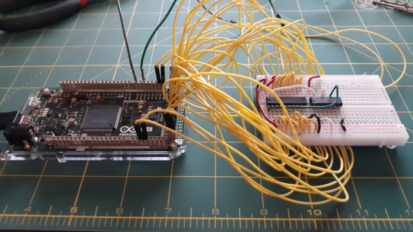
Thanks to [Nick Bild], there is, in the form of the “Schematic-o-matic”, which aims to automate the breadboard documentation process. The trick is using a breadboard where each bus bar is connected to an IO pin on an Arduino Due. A program runs through each point on the breadboard, running a continuity test to see if there’s a jumper connecting them. A Python program then uses the connection list, along with some basic information about where components are plugged into the board, to generate a KiCad schematic.

[Nick] admits the schematics are crude at this point, and that it’s a bit inconvenient to remove some components, like ICs, from the breadboard first to prevent false readings. But this seems like one of those things where getting 80% of the work done automatically and worrying about the rest later is a big win. Plus, we can see a path forward to automatic IC probing, and even measurement of passive components too. But even as it is, it’s a great tool.

Continue reading “Tricked-Out Breadboard Automatically Draws Schematics Of Whatever You Build”

Build An Everlasting Continuity Tester

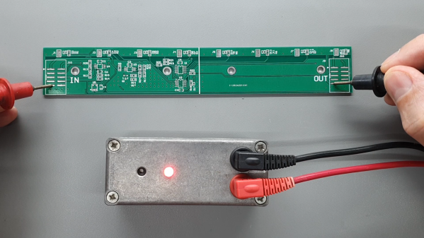
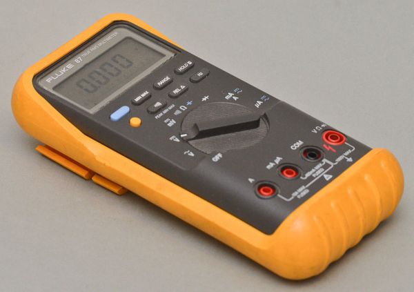
When you need a continuity tester at the bench, what do you reach for? Probably your multimeter, right? It may surprise you to know that the continuity tester in the meter isn’t all that sensitive, even if it’s the yellow expensive kind. [Leo]’s will beep even if there is 50Ω of resistance in the line.

Disgusted by modern commercial testers, [Leo] set out to make the ideal continuity tester in the spirit of old school tools that do one thing and do it really well. It had to be simple to use, always ready to go, and capable of measuring continuity at 5Ω or less resistance (video, embedded below).

There’s no power switch or even labels, because it doesn’t need any. Just put the probes where you want ’em, and it either beeps and lights the LED or it doesn’t. It looks simple, but inside that blast-resistant enclosure are lots of cool features that certainly make it seem like the ideal tester to us.

Our favorite has to be the transient blocking unit that works like a little circuit breaker. They’re used to protect circuits from lighting and electrostatic discharge by way of depletion-mode MOSFETs and switches to protected mode in under a microsecond. Watch [Leo] build this workbench necessity and then abuse test it with mains power after the break.

Making your own tools, however simple or complex is a great experience. If you want to up your speedy prototyping game, [Leo]’s got you covered there with a special scratching tool for hand-scribing copper PCBs. Continue reading “Build An Everlasting Continuity Tester”

Handy Continuity Tester Packs Multiple Modes Into A Tiny Package

From Leatherman multitools to oscilloscopes with built-in signal generators and protocol analyzers, there seems no end to tools with multiple personalities. Everybody loves multitaskers because they make it feel like you’re getting more bang for your buck, and in most cases that’s true. But a jack of all trades is seldom master of any, and there are times when even the humble multimeter isn’t the best tool for the job.

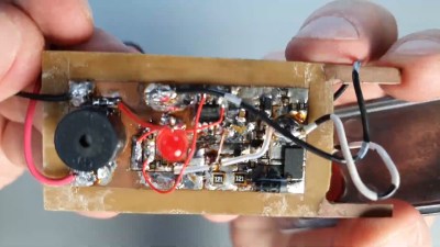
With that in mind, [sidsingh] has developed what we think is a very nice dedicated continuity tester. With a goal of using only parts on hand, he had to think small to fit everything into the case he had. So he started with a PIC10LF322 to support all the flavors of continuity testing he wanted to support. In addition to straight continuity, the tester can handle diode testing, detecting shorted or open diodes and even differentiating between regular and Schottky diodes. It also has an LED test mode and an interesting “discontinuity” testing mode — it only sounds its buzzer when continuity is broken. The video below shows that mode in action for finding intermittent cable faults, along with all the other modes.

For an ostensibly single-purpose tool, this tester still manages to pack a lot of tests into one very compact package. Simpler continuity testers are good, too — check out this cheap dollar store build, or this slightly more complicated unit based on an ATtiny85.

Continue reading “Handy Continuity Tester Packs Multiple Modes Into A Tiny Package”