Making USB Blaster Clones Work For Linux

The last time we checked in with [Downtown Doug Brown], he had some cheap Altera USB Blaster clones that didn’t want to work under Linux. The trick at that time was to change the device’s 24 MHz clock to 12 MHz. This month, he’s found some different ones that don’t work, but now the clock change doesn’t work. What’s the problem?

He also picked up a Terasic clone, which does work on Linux and is considered, according to [Doug], the best of the clones. The units were superficially similar. So what follows is a lot of USB tracing and dumping of the CPLD chip’s configuration.

Continue reading “Making USB Blaster Clones Work For Linux”

Z80 Single-Board Computer Looks Like It Could Have Been A Killer Product

Most retrocomputer builds seem to focus on either restoring old machines or rebuilding them from scratch. Either way, the goal is to get as close as possible to the original machine, and while we certainly respect those builds, there are other ways to celebrate the computers of yesterday, as this Z80 single-board computer nicely demonstrates.

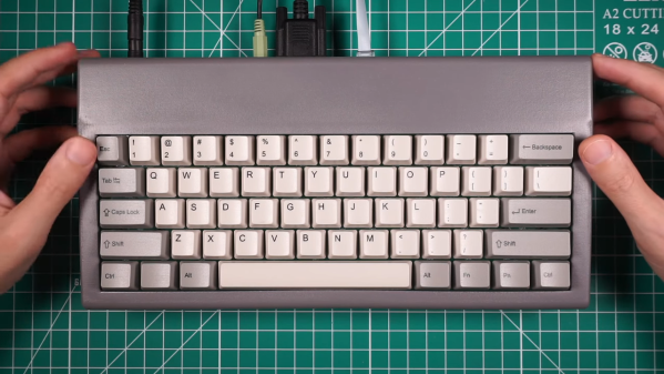
[Ivan Farafontov]’s SBC is sort of a “Z80 that never was” build, one that would almost have been possible back in the heyday of 8-bit computing, and would have made quite a splash if it had. Most of the peripheral chips are from Zilog and would have been found in many of the Z80 machines of the day, like the TRS-80 and ZX Spectrum. Where it goes off the old-school path is with the video section, which uses an Atmel CPLD chip and a dual-port RAM to drive a VGA monitor. It still looks the part, though, with a 256×192 pixel, 16-color display. The compact video section helps keep the overall footprint of this machine pretty small, at least by the standards of the old machines. The machine is barely larger than its custom keyboard, which is populated with mechanical switches and really nice-looking custom keycaps, and everything fits into a 3D-printed case.

The demo that starts at the 4:30 mark of the video below will be a nostalgia storm for a lot of readers, starting as it does with a version of Boulder Dash that [Ivan] wrote from scratch, along with the tile editor he used to create the sprites for the game. All the design files and code are available if you want to build your own, of course. We recently featured another Z80 that never was, but [Ivan]’s machine really makes a statement with its compact size and its capabilities.

Continue reading “Z80 Single-Board Computer Looks Like It Could Have Been A Killer Product”

PiStorm Brings Modern Muscle To The Amiga

The Amiga, well known as the best and greatest computer ever designed, is nonetheless a platform of yesteryear. Its 68K, and later PowerPC, architectures have both been abandoned by the mainstream, and its attractive grey industrial design no longer graces store shelves. That doesn’t mean the platform is dead however, with diehard shredders like [Claude Schwarz] working hard to keep it alive with projects like PiStorm.

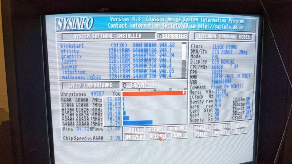
PiStorm is a Motorola 68K CPU emulator, running on a Raspberry PI 3A. The Pi uses its GPIOs to interact with a CPLD chip, which acts as the logic glue to allow the modern single board computer to emulate the Amiga’s original processor. However, it’s more than just an easy way to replace or upgrade a CPU. It also offers additional features, like retargetable graphics acceleration, SCSI disk emulation, and the ability to run whatever Kickstart ROM you so desire.

While the initial work has been done on a Pi 3A, [Claude] has also demonstrated some of the basic functionality running on a Pi CM4 too. The benchmarks are more fierce than a Beyoncé Super Bowl half time show, so if you need grunt on your classic Amiga, this could be the way to go. As a bonus, files to build your own are readily available on Github, which should make it a mite more accessible than other Amiga accelerator boards.

We wonder whether this accelerator could be used to hook the Amiga up to Spotify, a la this previous build. Likely, time will tell. Video after the break.

Continue reading “PiStorm Brings Modern Muscle To The Amiga”

Custom Controller Makes Turbomolecular Pump Suck

[Mark Aren] purchased a pair of Turbomolecular pumps (TMP) sans controllers, and then built an FPGA based BLDC controller for the Turbomolecular pumps. A TMP is similar to a jet turbine, consisting of several stages of alternating moving turbine blades and stationary stator blades, and having turbine rotation speeds ranging from 10,000 rpm to 90,000 rpm. TMP’s cannot exhaust directly to atmosphere, and must be combined with a backing (or roughing) pump to create a lower grade vacuum first. They find use in lots of applications such as electron microscopy, analytical sciences, semiconductors and lamp manufacturing. With the lamp industry rapidly embracing LEDs, many of the traditional lamp making lines are getting decommissioned, and if you are lucky, you can snag a TMP at a low cost – but it still will not be cheap by any means.

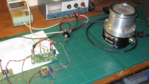
The two BOC-Edwards EXT255H Compound Molecular Pumps (PDF), that [Mark] bought did not have their accompanying EXC100E Turbomolecular Pump Controllers (PDF), and given pandemic related restrictions, he decided to build a controller of his own, using components and modules from his parts bin. The pump and controller user manuals offered only sketchy details about the sensored BLDC motor used in the pump. The low phase-to-phase resistance implied low drive voltage, and [Mark] decided to try running it at 24 V to start with. He already had experience using the Mitsubishi PS21245-E IGBT inverter bridge, and even though it was rated for much higher voltages, he knew that it would work just fine at 24 V too.

After figuring out a state machine for motor commutation that utilized PWM based adjustable current control, he implemented it on a 128 element FPGA board. Considering how expensive the TMP was, he wisely decided to first try out his driver on a smaller “expendable” BLDC motor. This whole process was non-trivial, since his available IGBT module was untested and undocumented, and required several tweaks before he could run it at the required 12 kHz PWM signals. His test motor was also undocumented, failing to run correctly when first hooked up. Fixing that issue meant having to disassemble the motor to check its internal wiring. Eventually, his efforts paid off, and he was able to safely run the TMP motor to confirm that his design worked.
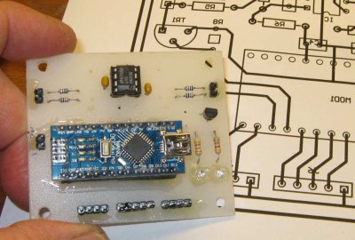
With FPGA code, IGBT wiring and power supply issues sorted, the next step was to add a supervisory micro-controller, using an Arduino Nano. Its functions included interfacing with a touch screen LCD as a user interface, communicating with the FPGA module, and controlling several relays to switch power to the motor power supply, the roughing pump, TMP cooling fan, and a solenoid for the vacuum vent. Spindle current is calculated by measuring voltage drop across shunt resistors on the low side of the IGBT. Motor speed is measured using one of the motor hall sensors, and a thermistor provides motor temperature sensing. [Mark]’s PCB fabrication technique seems a bit different too. Using an Excellon drill file, he drills holes in a piece of plastic using a laser cutter to create a bare board, and then solders copper tracks by hand.

His initial tests at atmospheric pressure (although not recommended unless you monitor pump temperature), resulted in 7300 rpm while consuming about 7 Amps before he had to shut it down. In further tests, after adding a roughing pump to the test setup, he was able to spin the TMP to 20,000 rpm while it consumed 0.6 A. Obviously, the pump is rated to operate at a higher voltage, possibly 48 V based on the values mentioned in the TMP controller manual. The project is still “work in progress” as [Mark] hopes to eventually drive the pump up to its specified 60,000 rpm operating speed. What is not clear is what he eventually intends to do with this piece of exotic machinery. All he mentions is that “he has recently taken an interest in high-vacuum systems and is interested in exploring the high-vacuum world of electron guns.”

Maybe [Mark] can compare notes with the Open Source Turbomolecular Pump Controller that we featured some time back. And if you’d like to be a little bit more adventurous and build you own TMP, we got you covered with this DIY Everyman’s Turbomolecular Pump.

Build One, Get Two: CPLD And STM32 Development On A Single Board

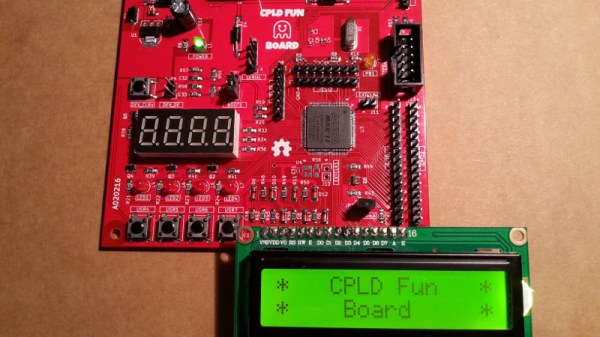
Programmable logic devices have claimed their place in the hobbyist world, with more and more projects showing up that feature either a CPLD or their bigger sibling, the FPGA. That place is rightfully earned — creating your own, custom digital circuitry not only adds flexibility, but opens up a whole new world of opportunities. However, this new realm can be overwhelming and scary at the same time. A great way to ease into this is combining the programmable logic with a general purpose MCU system that you already know and are comfortable with. [Just4Fun] did just that with the CPLD Fun Board, a development board connecting an Arduino compatible STM32F103 Cortex-M3 controller to an Altera MAX II CPLD.

The PCB itself has some standard development board equipment routed to the CPLD: LEDs, buttons, a seven-segment display, and additional GPIO. The rest of the CPLD’s pins are going straight to the STM32 and its SPI, I2C and UART pins. Let’s say you want to create your own SPI device. With the CPLD Fun Board, you can utilize all the pre-existing libraries on the STM32 and fully focus on the programmable logic part. Better yet, every connection from MCU to CPLD has its own pin header connection to attach your favorite measurement device for debugging. And in case you’re wondering — yes, you can attach external hardware to those connectors by setting either MCU or CPLD pins to Hi-Z.

The downside of all this is the need for proprietary design software and a dedicated programmer for the CPLD, which sadly is the everyday reality with programmable logic devices. [Just4Fun] did a great job though writing up a detailed step-by-step tutorial about setting up the environment and getting started with the board, but there are also other tutorials on getting started with CPLDs out there, in case you crave more.

Sega’s Game Gear Gets A Video Output

[EvilTim] dug deep into a classic system to finally give the Game Gear a proper video output.  The Game Gear was Sega’s answer to Nintendo’s Gameboy. Rushed to market, the Game Gear reused much of the hardware from the very popular Master System Console. The hardware wasn’t quite identical though – especially the cartridge slot. You couldn’t play Game Gear games on a Master System, and the game gear lacked an AV output, which meant gamers were stuck playing on a small fluorescent backlit LCD screen.

[EvilTim] wanted to play some of those retro titles on a regular TV using the original hardware. To accomplish this he had to start digging into the signals driving the Game Gear’s LCD. The Master System lineage was immediately apparent, as Game Gear’s LCD drive signals were similar in timing to those used to drive a TV. There was even a composite sync signal, which was unused on in the Game Gear.

[EvilTim] first designed a circuit using discrete ’74 series logic which would convert the LCD drive signals to SCART RGB. Of note is the construction technique used in this circuit. A tower of three 74HC374 chips allows [EvilTim] to create R, G, and B outputs without the need for a complex circuit board.

As pretty as a three-story chip tower is, [EvilTim] knew there was a better way. He re-spun the circuit with a 32 macrocell CPLD. This version also has an NTSC and PAL video encoder so those without a SCART interface can play too. If you’re not up to building your own, [EvilTim] sells these boards on his website.

We’ve seen some incredible retro gaming hacks over the years. From a NES inside a cartridge to incredible RetroPi builds. Hit the search bar and check it out!

Cracking The Sega Saturn After 20 Years

When it was released 20 years ago, the Sega Saturn was by far the most powerful video game console available. It was a revolutionary device, had incredible (for the time) graphics, and a huge library of IP Sega could draw from. The Saturn was quickly overshadowed by the Sony Playstation, and soon these devices found themselves unused, unloved, and fetching high prices on the collectors market.

After finding a Sega Saturn on a trip to Japan, [jhl] decided he would like to write some code for this machine. Unlike earlier consoles, where Flash cartridges are readily available, or later consoles, where writing directly to the on-board storage is easy, bringing up a development environment for the Saturn isn’t easy. The best method is installing a mod chip and working off of burned CDs. Instead of writing a game or two for the Saturn, [jhl] got distracted for a few years and developed an optical drive emulator.

cracking-the-sega-saturn-thumbAccording to [jhl], the design of the Sega Saturn is tremendously complicated. There’s an entire chip dedicated to controlling the CD drive, and after some serious reverse engineering work, [jhl] had it pretty much figured out. The question then was how to load data onto the Saturn. For that. [jhl] turned to the internal expansion port on the Saturn. This internal expansion port was designed to accept an MPEG decoder card for playing video CDs on the Saturn, but the connector presents the entire bus. By attaching a Game Boy Flash cartridge, [jhl] was able to dump the ROM on the CD controller.

With a little bit of work, a fast ARM microcontroller, and a CPLD for all the logic glue, [jhl] was built an adapter to push CD data to the Saturn through this internal expansion port. Not only is this a boon for homebrew Saturn development, but this build also completely replaces the CD drive in the Saturn – a common failure point in this 20-year-old machine.

The formal release for this ultimate Saturn crack isn’t out yet, but it’s coming shortly, allowing anyone who still has a Saturn to enjoy all those very blocky games and develop their own games. You can check out a short, amateur documentary made on [jhl]’s efforts below.

Continue reading “Cracking The Sega Saturn After 20 Years”