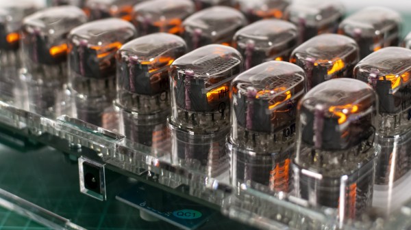
Rows of nixie tubes in clear acrylic

Binary Clock Lets The Nixies Glow

We’re not here to talk about another clock. Okay, we are, but the focus isn’t about whether or not it can tell time, it’s about taking a simple idea to an elegant conclusion. In all those ways, [Marcin Saj] produced a beautiful project. Most of the nixie clocks we see are base-ten, but this uses base-two for lots of warm glow from more than a dozen replaceable units.

There are three rows for hours, minutes, and seconds. The top and bottom rows are labeled with an “H” and “S” respectively displayed on IN-15B tubes, while the middle row shows an “M” from an IN-15A tube. The pluses and minuses light up on IN-12 models so you’ll need eighteen of them for the full light show, but you could skimp and use sixteen in twelve-hour mode since you don’t need to count to twenty-four. We won’t explain how to read time in binary, since you know, you’re here and all. The laser-cut acrylic is gorgeous with clear plastic next to those shiny nixies, but you have to recreate the files or buy the cut parts as we couldn’t find vector files amongst the code and schematics.

Silly rabbit, nixies aren’t just for clocks. You can roll your own, but they’re not child’s play.

Continue reading “Binary Clock Lets The Nixies Glow”

Hacked IKEA Air Quality Sensor Gets Custom PCB

Last month we brought word of the IKEA VINDRIKTNING, a $12 USD air quality sensor that could easily be upgraded to log data over the network with the addition of an ESP8266. It only took a couple of wires soldered to the original PCB, and since there was so much free space inside the enclosure, you didn’t even have to worry about fitting the parasitic microcontroller; just tape it to the inside of the case and button it back up.

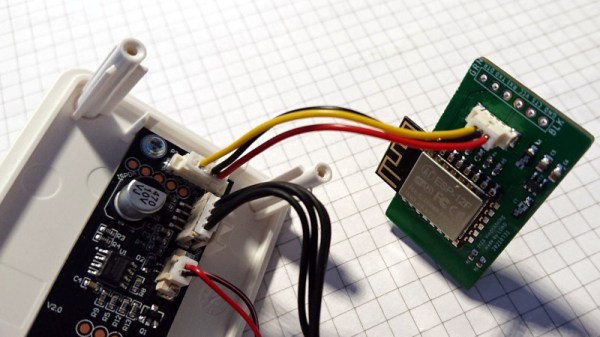
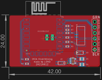
Now we’ve got nothing against the quick and dirty method around these parts, but if you’re looking for a slightly more tidy VINDRIKTNING modification, then check out this custom PCB designed by [lond]. This ESP-12F board features a AP2202 voltage regulator, Molex PicoBlade connectors, and a clever design that lets it slip right into a free area inside the sensor’s case. The project description says the finished product looks like it was installed from the factory, and we’re inclined to agree.

Nothing has changed on the software side, in fact, the ESP-12F gets flashed with the same firmware [Sören Beye] wrote for the Wemos D1 Mini used in his original modification. That said [lond] designed the circuit so the MCU can be easily reprogrammed with an FTDI cable, so just because you’re leaving the development board behind doesn’t mean you can’t continue to experiment with different firmware builds.

It’s always gratifying to see this kind of community development, whether or not it was intentionally organized. [lond] saw an interesting idea, found a way to improve its execution, and released the result out into the wild for others to benefit from. It wouldn’t be much of a stretch to say that this is exactly the kind of thing Hackaday is here to promote and facilitate, so if you ever find yourself inspired to take on a project by something you saw on these pages, be sure to drop us a line.

Custom Camera Flash Is Built For Stealth

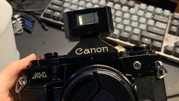
As [Joshua Bird] began his foray into the world of film photography, he was taken back by the old technology’s sheer hunger for light. Improvised lighting solutions yielded mixed results, and he soon realized he needed a true camera flash. However, all the options he found online were large and bulky; larger than the camera itself in some cases. To borrow his words, “[he] didn’t exactly want to show up to parties looking like the paparazzi”. So, he set about creating his own compact flash.

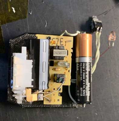
Impressed by the small size and simple operation of disposable camera flashes, [Joshua] lifted a module out of an old Fuji and based his design around it. An existing schematic allowed him to attach the firing circuitry to his Canon’s hot shoe without the risk of putting the capacitor’s 300 volts through the camera. With that done, he just had to model a 3D-printed case for the whole project and assemble it, using a few more parts from the donor disposable.

Of course, as it came from a camera that was supposed to be thrown in the trash, this flash was only designed for a specific shutter speed, aperture, and film. Bulkier off-the-shelf flashes have more settings available and are more capable in a variety of environments. But [Joshua] built exactly what he needed. He now has a sleek, low-profile external flash that works great in intimate settings. We’re excited to see the photographic results.

This is not the first photography hacker we’ve seen breathe new life into disposable flashes. Some people see far more than a piece of camera equipment in old flashes, though, with aesthetically stunning results.

[via reddit]

The Word Clock You Can Feel

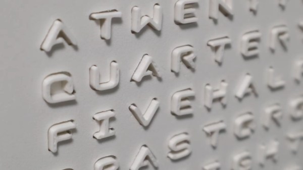
By this point, pretty much everyone has come across a word clock project, if not built one themselves. There’s just an appeal to looking at a clock and seeing the time in a more human form than mere digits on a face. But there are senses beyond sight. Have you ever heard a word clock? Have you ever felt a word clock? These are questions to which Hackaday’s own [Moritz Sivers] can now answer yes, because he’s gone through the extreme learning process involved in designing and building a haptic word clock driven with the power of magnets.

Individual letters of the display are actuated by a matrix of magnetic coils on custom PCBs. These work in a vaguely similar fashion to LED matrices, except they generate magnetic fields that can push or pull on a magnet instead of generating light. As such, there are a variety of different challenges to be tackled: from coil design, to driving the increased power consumption, to even considering how coils interact with their neighbors. Inspired by research on other haptic displays, [Moritz] used ferrous foil to make the magnets latch into place. This way, each letter will stay in its forward or back position without powering the coil to hold it there. Plus the letter remains more stable while nearby coils are activated.

Part of the fun of “ubiquitous” projects like word clocks is seeing how creative hackers can get to make their own creations stand out. Whether it’s a miniaturized version of classic designs or something simple and clean, we  love to see them all. Unsurprisingly, [Moritz] himself has impressed us with his unique take on word clocks in the past. (Editor’s note: that’s nothing compared to his cloud chambers!)

Check out the video below to see this display’s actuation in action. We’re absolutely in love with the satisfying *click* the magnets make as they latch into place.

Continue reading “The Word Clock You Can Feel”

30-Year-Old Macintosh SE/30 Gets A Brand New Logic Board

Some time ago, [Bolle] got the idea to redraw the Macintosh SE/30 schematics in Eagle. Progress was initially slow, but over the past month (and with some prodding and assistance from fellow forum frequenter [GeekDot]), he’s taken things a step further by creating a fully functional replacement Macintosh SE/30 logic board PCB.

By using the available schematics, the project didn’t even require much reverse engineering. Though he plans for more modernization in later iterations, this design is largely faithful to the original components and layout, ensuring that it is at least basically functional. He did update the real time clock battery to a CR2032 and, as a benefit of redrawing all the traces, he was able to use a 4-layer PCB in place of the costly 6-layer from Apple’s design.

The board came back from fabrication looking beautiful in blue; and, once he had it soldered up and plugged in, the old Mac booted on the very first try! A copy-paste mistake with the SCSI footprints led to some jumper wire bodging in order to get the hard drive working, but that problem has already been fixed in the next revision. And, otherwise, he’s seen no differences from the original after a few hours of runtime.

Recreating old Macintosh logic boards almost seems like its own hobby these days. With the design and fabrication capabilities now accessible to hobbyists, even projects that were once considered professional work are in reach. If you’re interested in making your own PCB designs, there are many resources available to help you get started. Alternatively, we have seen other ways to modernize your classic Macs.

[Thanks to techknight for the tip!]

chadaustin's sculpt keyboard test pads wired to protonC

Tether Tames Temperamental Typing

[chadaustin] has a favorite keyboard with a great ergonomic shape, key travel distance, and size, but after switching to Windows 10, the wireless connection introduced a terrible delay. Worse yet, the receiver is notoriously susceptible to interference from USB 3.0 hubs. To provide 128-bit AES encryption, the receiver is paired with the keyboard at the factory and cannot be replaced. If you lose that, you gain a highly ergonomic paper-weight. The solution for [chadaustin] was tethering the keyboard and receive several crash-courses in hardware hacking along the way. As evidenced by the responses to this project on ycombinator, many long-time fans of the Microsoft Sculpt Ergonomic Keyboard, introduced in 2013, suffer similar issues.

chadaustin's sculpt keyboard USB board layout
KiCad USB controller board layout

We really appreciate that [chadaustin] took an incremental approach, tackling one problem at a time and getting help from others along the way for first attempts at many complex steps. The proof-of-concept involved hand-soldering each lead from the keyboard matrix’s test pads to a QMK Proton C, which worked but couldn’t fit inside the keyboard’s case. For a more permanent and tidy solution, [chadaustin] tried a ribbon-cable breakout board and other microcontrollers, but none of those were compact enough to fit inside the case either. This required a custom PCB, another first for [chadaustin].

After a one-day intro to KiCad, [chadaustin] dug into the datasheets, completed a schematic for the board, and generously shared the process of choosing components and creating the layout. [chadaustin] ordered a board and found the mounting holes’ placement needed to be shifted.

With the full matrix mapped by [johnmilkspill], flashing QMK onto the AT90USB1286 controller went fairly smoothly. [chadaustin] chose to map both sides of the split spacebar back to the space key but did add a feature by repurposing the battery indicator LED to Caps Lock. And the results?

chadaustin's sculpt keyboard USB controller fit into case
USB controller fits into the plastic case, wires added to ISP for bootloader button

According to testing done with Is It Snappy?, the latency dropped from the wireless 78 ms down to 65 ms over USB. More importantly, this latency is now consistent, unaffected by USB hubs, and there is no receiver to lose. Of course, [chadaustin] has ideas for future improvement, including regaining the multimedia function keys, as these kinds of hacks are never really done; they are just in the current revision. No word on the fate of the detached number pad, but that likely needs its own tether and is a project for another day.

Thanks for the tip [Linus Söderlind]

A Breadboard Block For 8-Bit CPUs

Breadboard CPUs are a fantastic learning experience and require serious dedication and patience. Occasionally, CPU builders eschew their breadboards and fab their design onto a PCB. But this takes away the flexibility and some of the opportunity for learning that breadboard CPUs offer. [c0pperdragon] was doing the same sort of repetitive wiring from project to project as most 8-bit breadboard CPUs use memory, a bus, an IO controller, ROM, and a few other passive components.

Taking a compromise approach, [c0pperdragon] built a PCB that can be used as a building block in his custom CPUs which they have titled “ByteMachine”. A single row of 34 pins offer power, clock, reset, 19 address bus lines, 8 data bus lines, and a ROM selector. This means that the CPUs can fit on a single breadboard and can run faster as the impedance of the breadboard has less effect on the circuit. With 512 KB of RAM and 512 KB of ROM, in a ZIF socket for easy reprogramming, ByteMachine has plenty of space.

One drawback is the lack of IO. There is no dedicated address space as this would require decoding logic between the RAM and the CPU. [C0pperdragon] added a simple 8-bit output register provided by a 74-series logic IC. The data is displayed on 8 red LEDs and can be accessed via pins. Input is accomplished in a similar way with just 8 bits of digital input provided.

[C0pperdragon] has built the 65C02, 65C816Z84C00, and the i8088 with the ByteMachine. Each was documented with incredible schematics, pictures, and test programs on GitHub. Next time you’re looking to build a CPU on a breadboard, maybe start with a ByteMachine. In some ways, it might improve your learning experience as it makes the incredible mass of wires we’ve seen on other projects a tad more manageable.

Thanks [Reinhard Grafl] for sending this one in!