CADmium Moves CAD To The Browser

For plenty of computer users, the operating system of choice is largely a middleman on the way to the browser, which hosts the tools that are most important. There are even entire operating systems with little more than browser support, under the assumption that everything will be done in the browser eventually. We may be one step closer to that type of utopia as well with this software tool called CADmium which runs exclusively in a browser.

As the name implies, this is a computer-aided design (CAD) package which looks to build everything one would need for designing project models in a traditional CAD program like AutoCAD or FreeCAD, but without the burden of needing to carry local files around on a specific computer. [Matt], one of the creators of this ambitious project, lays out the basic structure of a CAD program from the constraint solver, boundary representation (in this case, a modern one built in Rust), the history tracker, and various other underpinnings of a program like this. The group hopes to standardize around JSON files as well, making it easy to make changes to designs on the fly in whatever browser the user happens to have on hand.

While this project is extremely early in the design stage, it looks like they have a fairly solid framework going to get this developed. That said, they are looking for some more help getting it off the ground. If you’ve ever wanted something like this in the browser, or maybe if you’ve ever contributed to the FreeCAD project and have some experience, this might be worth taking a look at.

An Umbrella Can Teach A Thing Or Two About Product Longevity

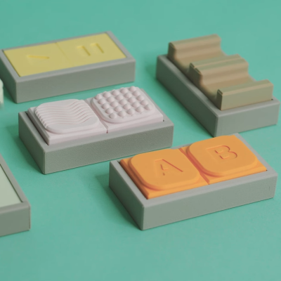
This time of year always brings a few gems from outside Hackaday’s usual circle, as students attending industrial design colleges release their final year projects, The worlds of art and engineering sit very close together at times, and theirs is a discipline which sits firmly astride that line. This is amply demonstrated by the work of [Charlie Humble-Thomas], who has taken an everyday object, the umbrella, and used it to pose the question: How long should objects last?

He explores the topic by making three different umbrellas, none of which we are guessing resemble those you could buy. The first is not particularly durable but is completely recyclable, the second is designed entirely with repairability in mind, while the third is hugely over-engineered and designed for durability. In each case the reader is intended to think about the impact of the umbrella before them.

What strikes us is how much better designed each one is than the typical cheap umbrella on sale today, with the polypropylene recyclable one being flimsy by design, but with a simplicity missing from its commercial counterpart. The durable one meanwhile is full of CNC parts, and carbon fiber.

If you’re hungry for more student work in this vein, we recently brought you this toasty typewriter.

This Typewriter Types Toast

As a writer it’s a pleasure to see one’s work appear from time to time on a physical medium. While newspapers may be shuffling slowly off this mortal coil, there are still a few opportunities to write for printed media. It’s safe to say that no Hackaday scribe has ever managed to have their work published on the medium in this hack though, because it’s a typewriter designed to type on toast.

The toaster-typewriter is the work of [Ritika Kedia], and it forms part of her thesis in product design at the Parsons School of Design, New York. It’s written up very much from an artistic rather than a tech perspective, but it’s no less ingenious for that in the way it uses letters formed from hot wire on a clay substrate, mounted on the end of the typewriter arms in front of a toaster.

We’re slightly sad to see that it only has three operable letters at the moment as it’s an artwork rather than a document machine, but we love the idea and wish she had time to develop it further with a full alphabet. You can see a short demo in the video below the break.

Continue reading “This Typewriter Types Toast”

Chip Mystery: The Case Of The Purloined Pin

Let’s face it — electronics are hard. Difficult concepts, tiny parts, inscrutable datasheets, and a hundred other factors make it easy to screw up in new and exciting ways. Sometimes the Magic Smoke is released, but more often things just don’t work even though they absolutely should, and no amount of banging your head on the bench seems to change things.

It’s at times like this that one questions their sanity, as [Gili Yankovitch] probably did when he discovered that not all CH32V003s are created equal. In an attempt to recreate the Linux-on-a-microcontroller project, [Gili] decided to go with the A4M6 variant of the dirt-cheap RISC-V microcontroller. This variant lives in a SOP16 package, which makes soldering a bit easier than either of the 20-pin versions, which come in either QFN or TSSOP packages.

Wisely checking the datasheet before proceeding, [Gili] was surprised and alarmed that the clock line for the SPI interface didn’t appear to be bonded out to a pin. Not believing his eyes, he turned to the ultimate source of truth and knowledge, where pretty much everyone came to the same conclusion: the vendor done screwed up.

Now, is this a bug, or is this a feature? Opinions will vary, of course. We assume that the company will claim it’s intentional to provide only two of the three pins needed to support a critical interface, while every end user who gets tripped up by this will certainly consider it a mistake. But forewarned is forearmed, as they say, and hats off to [Gili] for taking one for the team and letting the community know.

Arduino Gear Shift Indicator Finds ‘Em So You Won’t Grind ‘Em

Now, it’s been a shamefully long time since we’ve driven a car with a manual transmission, but as we recall it was pretty straightforward. It certainly didn’t require a lot of help with the shifting pattern, at least not enough to require a technical solution to know what gear you’re in. But then again, we suspect that’s not really the point of [upir]’s latest build.

Oh sure, it’s pretty cool to display your current gear selection on a little LCD screen using an Arduino. And [upir] promises a follow-up project where the display goes inside the shifter knob, which will be really cool. But if you take a look at the video below, you’ll see that the real value of this project is the stepwise approach he takes to create this project. [upir] spends most of the time in the video below simulating the hardware and the code of the project in Wokwi, which lets him make changes and tune the design up before committing anything to actual hardware.

That turned out to be particularly useful with this build since he chose to use analog Hall sensors to detect the shift lever position and didn’t know exactly how that would work. Wokwi let him quickly build a virtual prototype for one sensor (using a potentiometer as a stand-in, since the simulator lacked a Hall sensor model), then quickly expand to the four sensors needed to detect all six gear positions.

By the time his simulation was complete, the code was almost entirely written. [upir] also walks us through his toolchains for both designing the graphics and laying out the PCB, a non-trivial task given the odd layout. We particularly enjoyed the tip on making smooth curved traces around the oval cutout for the shift lever in the board.

The video below is on the longish side, but it’s chock full of great little tips. Check out some more of [upir]’s work, like his pimped-out potentiometer or his custom animations on 16×2 LCDs.

Continue reading “Arduino Gear Shift Indicator Finds ‘Em So You Won’t Grind ‘Em”

The Perils Of Return Path Gaps

The radio frequency world is full of mysteries, some of which seem to take a lifetime to master. And even then, it seems like there’s always something more to learn, and some new subtlety that can turn a good design on paper into a nightmare of unwanted interference and unexpected consequences in the real world.

As [Ken Wyatt] aptly demonstrates in the video below, where you put gaps in return paths on a PCB is one way to really screw things up. His demo system is simple: a pair of insulated wires running from the center pins on BNC jacks and running along the surface of a piece of copper-clad board to simulate a PCB trace. The end of each wire is connected to the board’s ground plane through a 50 ohm resistor, with one wire running over a narrow slot cut into the board. A harmonics-rich signal is fed into each trace while an H-field EMC probe connected to a spectrum analyzer is run along the length of the trace.

With the trace running over the solid ground plane, the harmonics are plentiful, as expected, but they fall off very quickly away from the trace. But over on the trace with the gapped return trace it’s a far different story. The harmonics are still there, but they’re about 5 dBmV higher in the vicinity of the gap. [Ken] also uses the probe to show just how far from the signal trace the return path extends to get around the gap. And even worse, the gap makes it so that harmonics are detectable on the unpowered trace. He also uses a current probe to show how common-mode current will radiate from a long conductor attached to the backplane, and that it’s about 20 dB higher with the gapped trace.

Hats off to [Ken] for this simple explanation and vivid reminder to watch return paths on clock traces and other high-frequency signals. Need an EMC probe to check your work? A bit of rigid coax and an SDR are all you needContinue reading “The Perils Of Return Path Gaps”

A Deep Dive Into Quadcopter Controls

In the old days, building a quadcopter or drone required a lot of hacking together of various components from the motors to the batteries and even the control software. Not so much anymore, with quadcopters of all sizes ready to go literally out-of-the-box. While this has resulted in a number of knock-on effects such as FAA regulations for drone pilots, it’s also let us disconnect a little bit from the more interesting control systems these unique aircraft have. A group at Cornell wanted to take a closer look into the control systems for drones and built this one-dimensional quadcopter to experiment with.

The drone is only capable of flying in one dimension to allow the project to more easily fit into the four-week schedule of the class, so it’s restricted to travel along a vertical rod (which also improves the safety of the lab).  The drone knows its current position using an on-board IMU and can be commanded to move to a different position, but it first has to calculate the movements it needs to make as well as making use of a PID control system to make its movements as smooth as possible. The movements are translated into commands to the individual propellers which get their power from a circuit designed from scratch for this build.

All of the components of the project were built specifically for this drone, including the drone platform itself which was 3D printed to hold the microcontroller, motors, and accommodate the rod that allows it to travel up and down. There were some challenges such as having to move the microcontroller off of the platform and boosting the current-handling capacity of the power supply to the motors. Controlling quadcopters, even in just one dimension, is a complex topic when building everything from the ground up, but this guide goes some more of the details of PID controllers and how they help quadcopters maintain their position.

Continue reading “A Deep Dive Into Quadcopter Controls”