Injection molding is one of the technologies that makes the world go round. But what does it actually look like to go through the whole process to get a part made? [Achim Haug] wrote up a blog post that does a fantastic job of explaining what to expect when getting plastic enclosures injection molded in China.
Injection molding a part requires making a custom mold, which is then used by an injection molding machine in a shop to crank out parts. These are two separate jobs, but in China the typical business model is for a supplier to quote a price for both the mold as well as the part production. [Achim] describes not only what navigating that whole process was like, but also goes into detail on what important lessons were learned and shares important tips.
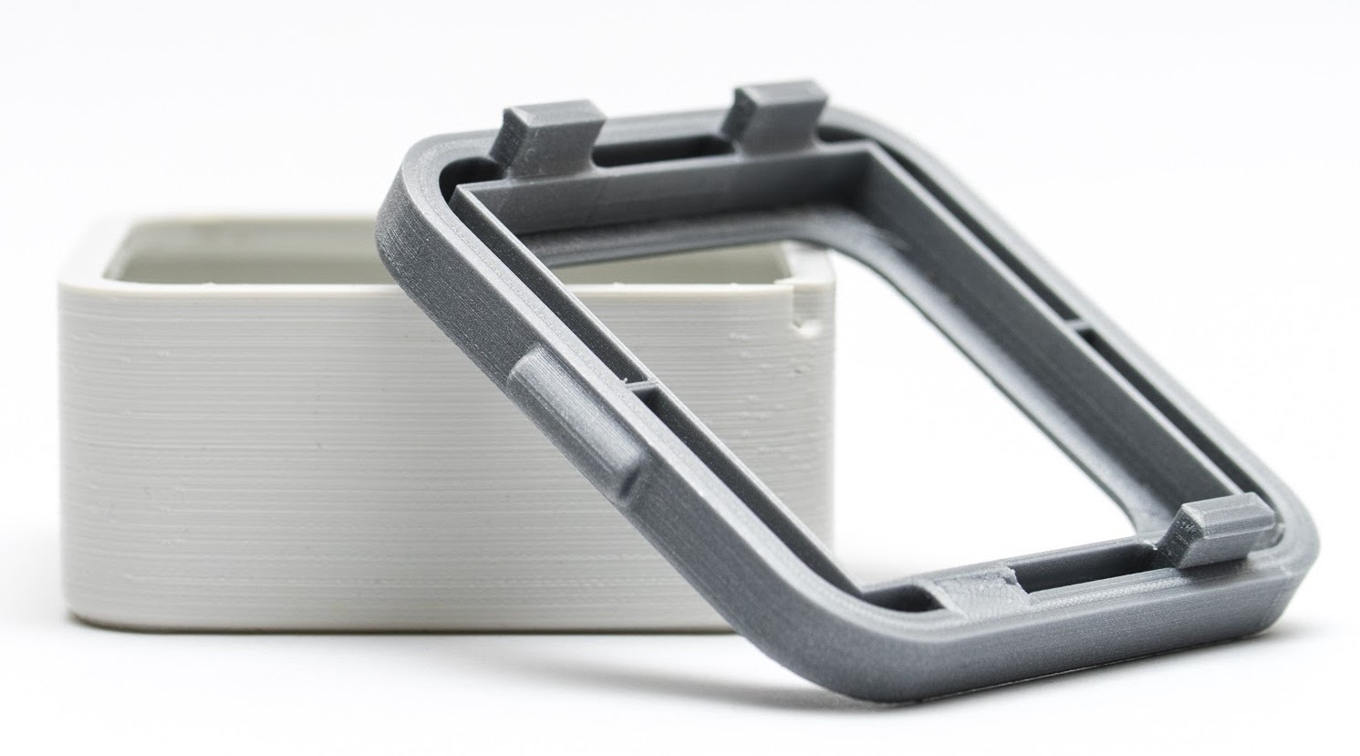
One of the biggest takeaways is to design the part with injection molding in mind right from the start. That means things like avoiding undercuts and changes in part thickness, as well as thinking about where the inevitable mold line will end up.
[Achim] found that hiring a been-there-done-that mold expert as a consultant to review things was a huge help, and well worth the money. As with any serious engineering undertaking, apparently small features or changes can have an outsized impact on costs, and an expert can recognize and navigate those.
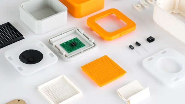
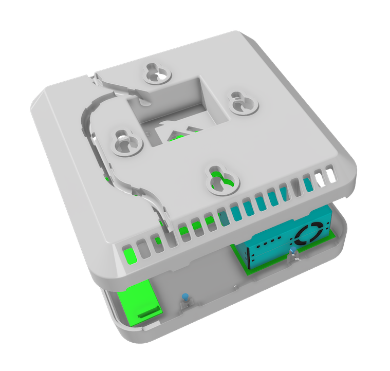
In the end, [Achim] says that getting their air quality monitor enclosures injection molded was a great experience and they are very happy with the results, so long as one is willing to put the work in up front. Once the mold has been made, downstream changes can be very costly to make.
[Achim]’s beginning-to-end overview is bound to be useful to anyone looking to actually navigate the process, and we have a few other resources to point you to if you’re curious to learn more. There are basic design concerns to keep in mind when designing parts to make moving to injection molding easier. Some injection molding techniques have even proven useful for 3D printing, such as using crush ribs to accommodate inserted hardware like bearings. Finally, shadow lines can help give an enclosure a consistent look, while helping to conceal mold lines.