A little over a month ago, we featured a project from [Igor] who built 64 bits of DRAM from scratch using discrete components. Jokes about memory pricing aside, he did have a use case for such a small amount of memory — he is using it in a custom-built drum machine. But featuring the memory build and not the drum machine was perhaps putting the cart before the horse, so in this video, [Igor] shows off the construction of each part of his impressive 16- or 64-step sequence drum machine.
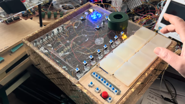
This isn’t Igor’s first drum machine, either, although his previous build was a bit more limited. It had fewer steps in the sequence and didn’t quite have the range of his newer model. The upgraded version can play more steps but also includes force-sensitive drum pads based on piezo sensors and more voices (drums) as well. Each voice is built electronically using various op-amps and passive components, and [Igor] has the schematics for each of them, as well as every other part of the drum machine, for those looking to recreate any part of this on their own. There’s a lot going on in this lengthy video as well, so for the musically inclined, it’s worth taking a look in full.
Now that our horse is in the correct position in front of the cart, it’s worth going back and looking at the memory build if you missed it when it first ran. A small amount of memory makes the machine programmable rather than just playable, and truly expands the capabilities of a machine like this in the recording studio.