[BuyItFixIt] is well known as a dab hand at, well, fixing things… and presumably buying them, too. Recently, they received an email calling for help of the former kind. One of their Australian viewers owned the same model of tractor, but with a dead digital dash. Thankfully, help was at hand!
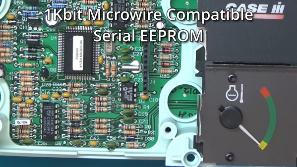
The problem turned out to be due to a dead EEPROM on the Australian tractor. In contrast, [BuyItFixIt] had a perfectly working dashboard on their tractor. Thus, they set about disassembling the dash and dumping the EEPROM to try and sort the stricken farm implement. This posed some risk of ending up with two dead dashboards, necessitating a careful hand. In any case, the Case tractor had a fairly simple dash with a majority of through-hole components, making it fairly easy to work with. The Microchip 93LC46B chip was in a DIP package, and was removed with the aid of some low-melting point solder in short order. The contents of the EEPROM were then dumped to a file using a XGecu T48 programmer.
With the file sent off via email, the Australian tractor owner flashed a fresh EEPROM and reinstalled it in their cluster. They were greeted with success, with the only complication being that the hours reading on the cluster had to be corrected to match the previous reading on their machine.
It’s a fairly simple story of fixing an embedded system, but it’s an educational one. It also comes with a deeper dive into how the CASE dashboard works. Just about anyone with basic electronic skills could pull this off and save an entire tractor in the process. It’s great to see these jobs documented so that we can all learn useful basic skills like these. Video after the break.
Continue reading “Fixing A Tractor Dashboard From Over 10,000 Miles Away”

