More GPIOs For The ESP8266

The ESP8266 is an incredible piece of hardware; it’s a WiFi module controllable over a serial port, it’s five freaking dollars, and if that’s not enough, there’s a microcontroller on board. Until there’s a new radio standard, this is the Internet Of Things module.

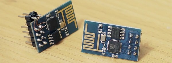
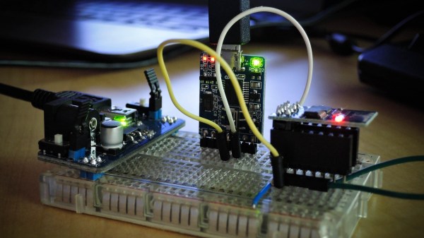
The most common version of the ESP, the -01 version, only has a 2×4 row of pins for serial, power, configuration, and two lines of GPIO. It’s a shame that module only has two GPIOs, but if you’re good enough with a soldering iron you can get a few more. It took a lot of careful soldering, but [Hugatry] managed to break out two more GPIOs on this tiny module.

According to [Hugatry] a lot of patience to solder those wires onto those tiny pads, but after finishing this little proof of concept he discovered a Russian hacker managed to tap into four extra GPIOs on the ESP8266-01 module (Google Translatrix).

As a proof of concept, it’s great, but there’s more than one ESP module out there. If you’re looking for a cheap WiFi module, check out the ESP-03, -04, or -07; they have nice castellated pins that are exceptionally easy to solder to.

Video below.
Continue reading “More GPIOs For The ESP8266”

ESP8266 Keeps An Eye On Your Batteries

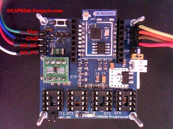
There are many more things to know about a battery than its voltage and current output at any given moment, and most of them can’t be measured with a standard multimeter unless you also stand there for a long time with an Excel spreadsheet. The most useful information is battery capacity, which can tell you how much time is left until the battery is fully charged or fully discharged. [TJ] set out to create a battery data harvester, and used the ubiquitous ESP8266 to make a fully-featured battery monitor.

Measuring battery capacity is pretty straightforward but it does take time. A battery is first benchmarked to find its ideal capacity, and then future voltage and current readings can be taken and compared to the benchmark test to determine the present capacity of the battery. The ESP8266 is a relatively good choice for this kind of work. Its WiFi connection allows it to report its information to a server which will store the data and make it available for the user to see.

The first page of this project details building the actual module, and the second page outlines how to get that module to communicate with the server. Once you’ve built all of this, you can use it to monitor your whole-house UPS backup system or the battery in your solar-powered truck. There is quite a bit of information available on the project site for recreating the build yourself, and there’s also a video below which shows its operation.

Continue reading “ESP8266 Keeps An Eye On Your Batteries”

An Amazon Dash-Like Button For The ESP8266

The Amazon Dash Button is a tiny piece of hardware that contains a single pushbutton, a WiFi module, and a nice, shiny corporate logo. Press the button, and products with that logo will be delivered to your house. An impressive bit of marketing, at least. With small, cheap WiFi modules like the ESP8266, it was only a matter of time until something an Amazon Dash clone was developed.

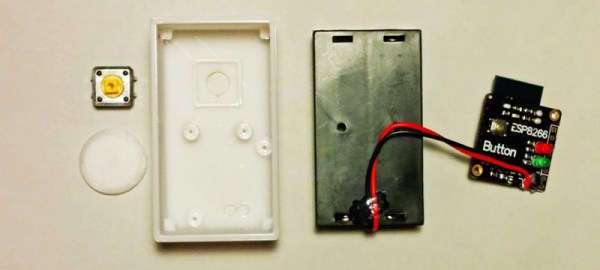
[deqing] created an ESP8266 Dash Button using the ESP-12 module, a button, a 3D printed case, and a pair of AA batteries. Electronically, it’s extremely simple; press the button, the ESP will wake up, request a URL, and put itself back to sleep. That’s all you need to do when you’re replicating the functionality of the Amazon Dash Button – the server will take care of the rest.

To configure the ESP8266, [dequng] is using the ESP-TOUCH app for Android, and setting up new functionality in this ESP button is as simple as putting a URL in the button’s Flash.

Not only is this a great build that has literally hundreds of different uses, it’s also not a breakout board for the ESP8266. It’s great that we’re finally seeing some builds using this cheap WiFi chip in the real world.

Obviously the actual Dash buttons include authentication that this one does not. We recently saw a teardown of the original hardware. We’re still waiting for in-depth analysis of the data squirted to the internet when an order is placed with it, though.

Arduino IDE Becomes More Open, Less Snarky

Version 1.6.4 of the Arduino IDE has been out for a little while now, and it has a couple of notable changes. To our eyes, the most interesting change makes adding support for non-standard boards and their configurations within the Arduino IDE a lot simpler. We’ll get into details below.

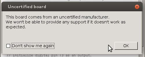
unnamedBut before that, it’s time to bid farewell to the cheeky little popup window that would deliver a warning message when using a board bearing the USB IDs of their former-partner-turned-competitor. We absolutely agree with [Massimo] that the issues between Arduino SRL / Smart Projects and Arduino LLC are well-enough known in the community, and that it’s time for the popup to fade away.
Now on to the meat of this post. The new “Board Manager” functionality makes it significantly easier for other non-Arduino products to be programmed within the Arduino IDE. Adafruit has a tutorial on using the Board Manager functionality with their products, and it basically boils down to “enter the right URL, click on the boards you want, download, restart Arduino, bam!”

The list of unofficially supported third-party boards is still a bit short, but it includes some stellar entries. For instance, Adafruit has provided the files needed for the ESP8266, which recently received the Arduino treatment. This means that you can simply point your IDE at Adafruit’s URL, and it’ll set you up with everything needed to develop for the ESP8266 from within the comfy Arduino IDE.

Continue reading “Arduino IDE Becomes More Open, Less Snarky”

Hackaday Prize Entry : Subterranean Positioning System

There are numerous instances where we need to know our location, but cannot do so due to GPS / GSM signals being unavailable and/or unreachable on our Smart Phones. [Blecky] is working on SubPos to solve this problem. It’s a WiFi-based positioning system that can be used where GPS can’t.

SubPos does not need expensive licensing, specialized hardware, laborious area profiling or reliance on data connectivity (connection to database/cellphone coverage). It works independently of, or alongside, GPS/Wi-Fi Positioning Systems (WPS)/Indoor Positioning Systems (IPS) as an additional positioning data source by exploiting hardware commonly available.

As long as SubPos nodes are populated, all a user wishing to determine their location underground or indoors needs to do is use a Wi-Fi receiver.  This can be useful in places such as metro lines, shopping malls, car parks, art galleries or conference centers – essentially anyplace GPS doesn’t penetrate. SubPos defines an accurate method for subterranean positioning in different environments by exploiting all the capabilities of Wi-Fi. SubPos Nodes or existing Wi-Fi access points are used to transmit encoded information in a standard Wi-Fi beacon frame which is then used for position triangulation.

The SubPos Nodes operate much like GPS satellites, except that instead of using precise timing to calculate distance between a transmitter and receiver, SubPos uses coded transmitter information as well as the client’s received signal strength. Watch a demo video after the break.


The 2015 Hackaday Prize is sponsored by:

Continue reading “Hackaday Prize Entry : Subterranean Positioning System”

A Tool For Spying On Serial Data

[Piotr] was working on a recent Arduino project when he ran into a problem. He was having trouble getting his Arduino Pro Mini to communicate with an ESP8266 module. He needed a way to snoop on the back and forth serial communications. Since he didn’t have a specialized tool for this task, [Piotr] ended up building his own.

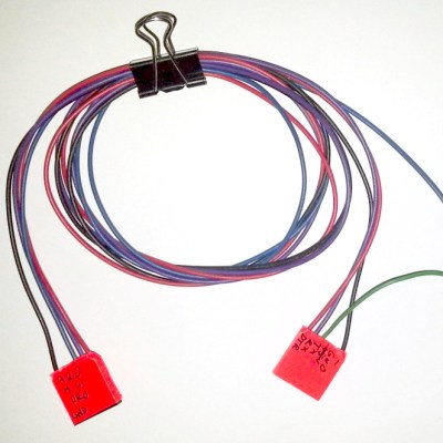
spying-on-serial-thumbThe setup is pretty simple. You start with a standard serial cable containing the TX, RX, DTR, and GND wires. This cable connects the Arduino to the ESP8266 WiFi module. The TX and RX lines are then tapped into. Each wire is routed to the RX pin of two different serial to USB adapters. This way, the data being sent from the Arduino shows up on one COM port and the data being transmitted from the module shows up on the other.

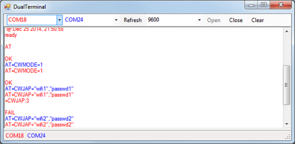
The next piece of the puzzle was coming up with a way to see the data more clearly. [Piotr] could have opened two serial terminals simultaneously, but this wasn’t ideal because it would be difficult to compare the timing of the data. Instead, [Piotr] spent less than an hour writing his own simple serial terminal. This one connects to two COM ports at the same time and prints the data on the same screen. The data from each COM port is displayed in a separate color to make it easy to differentiate. The schematic and source code to this project can be found on [Piotr’s] website.

Review: HUZZAH Is The ESP8266 WiFi Setup You Need

A little board that adds WiFi to any project for a few hundreds of pennies has been all the rage for at least half a year. I am referring to the ESP8266 and this product is a marrige of one of those WiFi modules with the support hardware required to get it running. This week I’m reviewing the HUZZAH ESP8266 Breakout by Adafruit Industries.

If you saw the article [cnlohr] woite for us about direct programming this board you will know that a good chunk of that post covered what you need to do just to get the module into programming mode. This required adding a regulated 3.3V source, and a way to pull one of the pins to ground when resetting the power rail. Not only does the HUZZAH take care of that for you, it turns the non-breadboard friendly module into a DIP form factor while breaking out way more pins than the most common module offers. All of this and the price tag is just $9.95. Join me after the break for the complete run-down.

Continue reading “Review: HUZZAH Is The ESP8266 WiFi Setup You Need”