There’s a school of thought that says that to fully understand something, you need to build it yourself. OK, we’re not sure it’s really a school of thought, but that describes a heck of a lot of projects around these parts.
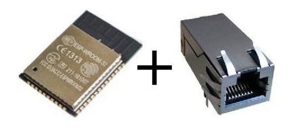
[Tim] aka [mitxela] wrote kiloboot partly because he wanted an Ethernet-capable Trivial File Transfer Protocol (TFTP) bootloader for an ATMega-powered project, and partly because he wanted to understand the Internet. See, if you’re writing a bootloader, you’ve got a limited amount of space and no device drivers or libraries of any kind to fall back on, so you’re going to learn your topic of choice the hard way.
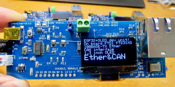
[Tim]’s writeup of the odyssey of cramming so much into 1,000 bytes of code is fantastic. While explaining the Internet takes significantly more space than the Ethernet-capable bootloader itself, we’d wager that you’ll enjoy the compressed overview of UDP, IP, TFTP, and AVR bootloader wizardry as much as we did. And yes, at the end of the day, you’ve also got an Internet-flashable Arduino, which is just what the doctor ordered if you’re building a simple wired IoT device and you get tired of running down to the basement to upload new firmware.
Oh, and in case you hadn’t noticed, cramming an Ethernet bootloader into 1 kB is amazing.
Speaking of bootloaders, if you’re building an I2C slave device out of an ATtiny85¸ you’ll want to check out this bootloader that runs on the tiny chip.